Method and apparatus for processing positive displacement drill bearing

A technology of screw drilling tools and bearings, applied in the direction of feeding devices, manufacturing tools, metal processing equipment, etc., can solve the problems of accelerated tool damage, deep pit curling on the surface, large tool turning area, etc., and achieve enhanced layer density Increased height, uniform subgrain structure refinement, and continuous and complete metal streamlines

Inactive Publication Date: 2008-10-29
李元甲
View PDF0 Cites 6 Cited by
  • Summary
  • Abstract
  • Description
  • Claims
  • Application Information

AI Technical Summary

Problems solved by technology

[0003] Due to the technical level of the operator or the failure of the equipment, during the forging process, it is easy to cause deformation of the blank workpiece, deep pit curling on the surface, etc., so that the blank does not meet the size requirements and is scrapped
Especially in the turning of bearing outer ring and inner ring blanks, there are many problems: ①During the rough turning process, curling and deep pits often appear on the datum surface. If the selection is not good, the workpiece will be scrapped directly. The alloy cutter head is easily damaged in an instant, which increases the cost
②In the process of finish turning, most of the scale on the surface of the blank is turned off during rough turning, but the turning has not yet reached the predetermined size, and continued turning will waste materials and power resources in vain
④Turning the R raceway is the most difficult and important part in the machining process. The turning area of ​​the tool is large and the heat is too fast, which will accelerate the damage of the tool

Method used


Image

  • Method and apparatus for processing positive displacement drill bearing
  • Method and apparatus for processing positive displacement drill bearing
  • Method and apparatus for processing positive displacement drill bearing

Examples


Embodiment Construction

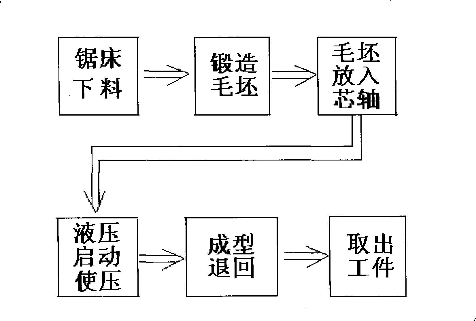
[0041] Such as figure 1 , 2 , 3, 4, 5, 6, 7, and 8 show: a method for processing screw drilling tool bearings is to adopt cold rolling process to process screw drilling tool bearings, and the steps are as follows:

[0042] 1) Processing the blank of the outer sleeve or the inner sleeve of the bearing: use 55SiMoVA round steel with strong plasticity, with a diameter of Φ60mm-Φ140mm; calculate the length of the round steel according to the model of the drilling tool bearing, cut it into small pieces with a sawing machine, and then place it Heat it in the furnace to about 500-700 degrees, then take it out and forge it into a ring shape with an air hammer, and then use a hole reaming machine to expand the height and diameter of the inner circle and outer circle to the predetermined size of the bearing outer shell blank (22a) or bearing inner Cover blank 22b); The outer diameter of the outer jacket and the outer diameter of the inner sleeve of the same model are 8%-30% smaller tha...


PUM

PropertyMeasurementUnit
diameteraaaaaaaaaa

Abstract

The invention discloses a method and a device for processing a bearing of a screw drill. The method adopts cold-rolling technique to process, firstly, an external sleeve blank or an internal sleeve blank of the bearing are processed; then the bearing of the screw drill is coldly rolled; a hydraulic oil cylinder (1) pushes a rolling wheel (7) to move downwards to be contacted with the bearing blank arranged on a rolling core roller (10) by pressurizing, thus lead the rolling wheel (7) to be parallel with the central shaft of the rolling core roller (10) and lead the rolling core roller to be contacted with the drive wheel (12) of a rotating mechanism; a coupler (14) connected with a motor (16) by a reducer drives the drive wheel and a driven wheel (13) to lead the rolling core roller to rotate; the rolling wheel (7) continuously puts pressure on the bearing blank until the bearing blank is deformed to achieve workpiece shaping standard. The invention can remarkably improve the surface fatigue intensity of a part, can eliminate a lathe machining process and can lead the utilization rate of materials to be improved from the former 45 percent to over 75 percent, which leads the power consumption of the device to be greatly reduced.

Description

technical field [0001] The invention relates to the technical field of bearing processing, and is particularly suitable for a method and device for processing screw drilling tool bearings. Background technique [0002] At present, in the mechanical industry, the prior art of processing screw drilling tool bearings generally adopts: heating and forging round steel to complete the diameter into bearing outer ring and inner ring blanks. Then, the bearing outer ring and inner ring blanks are multi-tool turned by lathe, which is usually divided into four processes: first, the black oxide skin on the surface of the forged blank is turned off. Use one of the planes as a reference to turn the other plane and the inner circle, and then turn the other plane and the outer circle in turn, commonly known as rough turning. Secondly, repeat the previous process on the blank after rough turning, commonly known as fine turning. Thirdly, in order to prevent the sharp edge of the workpiece f...

Claims


Application Information

Patent Timeline
Patent Type & Authority Applications(China)
IPC IPC(8): B23P15/00B21K1/05B21H1/06B21H9/00
Inventor 李元甲李社军
Owner 李元甲
Why Eureka
Try Eureka