Floating cable

A floating cable and inner sheath technology, applied in the direction of floating cables, insulated cables, cables, etc., can solve the problems of paralysis of conductive cores, difficult to meet the cable, difficult processing, etc., to meet the requirements of frequent bending without damage, convenient Processing and production, the effect of simple internal structure

Active Publication Date: 2008-11-05
SUZHOU CABLEPLUS PHOTOELECTRIC TECH
View PDF2 Cites 13 Cited by
  • Summary
  • Abstract
  • Description
  • Claims
  • Application Information

AI Technical Summary

Problems solved by technology

The problem solved by this patent solution is: light weight, can float on the water surface and is suitable for cables that need to be retracted frequently
But the disadvantages are: because the foamed polyethylene material is filled inside the cable, the structure is complex, the processing is difficult, the production efficiency is low, and the disadvantages of industrial production cannot be realized.
However, the applicant believes that the floating cable recommended by the above-mentioned patent has the following deficiencies and is not suitable for use as a power transmission carrier in operations such as submarine drilling, submarine natural gas survey, marine rescue, salvage, and scientific research.
One of its deficiencies is that it is difficult to meet the flexible requirements that the cable should have that is frequently bent and not easy to cause dam

Method used


Image

  • Floating cable

Examples


Embodiment 1

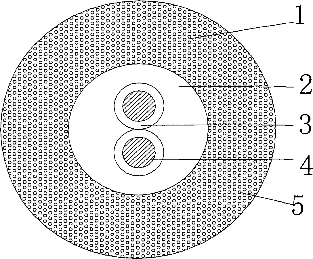
[0021] Please refer to the accompanying drawings in detail. From the profile of the cable structure, that is, the cross section, it can be clearly seen that the conductor 4 is located in the middle. 4 Select the tinned copper wire with a diameter of 0.05mm to twist itself into a bundled wire (also called a bundled wire), and then twist the twisted bundled wires to each other, so as to obtain a twisted wire that is a conductor. On the outside, the equipment commonly used in the wire and cable industry is used to cover polyolefin or polyethylene or polyvinyl chloride material on the outside of the conductor 4 to form a coating insulating sheath 3. In this example, polyvinyl chloride is used, and the thickness of the insulating sheath 3 is controlled at 0.2 ~ 2mm. In this example it is 0.2mm. More specifically, the insulating sheath 3 is extruded outside the conductor 4 shown in the figure to wrap the inner sheath 2. The material of the inner sheath 2 is thermoplastic elastomer T...

Embodiment 2

[0023] The diagram is omitted, only the number of conductors 4 is changed to 5, the material constituting the conductors is changed to an annealed bare copper wire with a diameter of 0.2 mm, the insulating sheath 3 is changed to polyolefin, and the thickness of the insulating sheath 3 is changed to 1 mm. The thickness of cover 2 is changed to 1 mm, the weight ratio of thermoplastic elastomer (TPE): foaming agent: lubricating oil is changed to 100: 1.2: 1.5, and the main component of thermoplastic elastomer (TPE) is changed to styrene block copolymer (SBS), the thickness of outer sheath 1 is changed into 2.5mm, and all the other are all the same as the description to embodiment 1.

Embodiment 3

[0025] The diagram is omitted, only the number of conductor 4 is changed to 1, the material constituting the conductor is changed to an annealed bare copper wire with a diameter of 0.5mm, the insulating sheath 3 is changed to polyethylene, and the thickness of the insulating sheath 3 is changed to 2mm. The thickness of cover 2 is changed to 2 mm, the weight ratio of thermoplastic elastomer (TPE): foaming agent: lubricating oil is changed to 100: 1.5: 2, the thickness of outer sheath 1 is changed to 5 mm, and the rest are the same as in Example 1 description of.


PUM

PropertyMeasurementUnit
Diameteraaaaaaaaaa
Thicknessaaaaaaaaaa
Thicknessaaaaaaaaaa

Abstract

A floadting cable includes a conductor coated with the insulated sheath, an inner sheath and an outer sheath, wherein the inner sheath is made of the thermoplastic elastomer coated on the insulation sheath of the conductor; the outer sheath is made of the mixtures of the thermoplastic elastomer, the foaming agent and the lubricant, which are coated on the outside of the inner sheath in definite amounts by weight after being mixed to form the foaming layer, and foaming micropores are formed in the foaming layer. The cable has the advantages of floating on the water because the global density of the cable is smaller than 1, which is convenient to maintain; providing with excellent global density and the frequent bending tolerance; mixing the foaming agent into the outer sheath, wherein airtight foaming micropores are formed in the outer sheath to constitute the foaming layer in the extruding process; the foaming layer adopts the conventional extruding device in the cable industry to coat on the outside of the inner sheath, which not only leads the inner structure of the floating cable with simple structure, but also is convenient to process with high production efficiency, which is suitable for the industrialization volume production.

Description

technical field [0001] The invention relates to a floating cable, which is suitable for power transmission in water operations. Background technique [0002] In the prior art, common water-blocking cables are used as cables for power transmission in most water operation equipment, and their weight is relatively heavy, and they all sink to the bottom of the water with the equipment during use. This kind of water-blocking cables is extremely easy to Scratching with hard objects on the seabed or river bed will cause damage to the cable, thereby reducing the service life of the cable; in addition, this kind of cable is not suitable for use in water operations because it is prone to knotting and entanglement when retracting and unwinding. Cables that are often retracted. [0003] In response to the above problems, some domestic cable manufacturers have also developed cables that can float on the water. Usually, these floating cables are filled with foam materials or a piece of f...

Claims


Application Information

Patent Timeline
IPC IPC(8): H01B7/12H01B7/17H01B3/44
Inventor 詹祖根陈良简爱莲
Owner SUZHOU CABLEPLUS PHOTOELECTRIC TECH
Why Eureka
Try Eureka