An Antenna Channel Detection Method Based on Six-Port Circuit

A channel detection and six-port technology, which is applied in wireless communication, electrical components, transmission monitoring, etc., can solve the problems of inconvenient engineering application and the inability to accurately know the antenna status of the electronic tag reader

Inactive Publication Date: 2011-12-21
INVENGO INFORMATION TECH
View PDF0 Cites 3 Cited by
  • Summary
  • Abstract
  • Description
  • Claims
  • Application Information

AI Technical Summary

Problems solved by technology

So far, there is no simple, fast and reliable method to determine whether the antenna matches the six ports and whether the noise meets the requirements, so that the status of the antenna of the electronic tag reader cannot be accurately known, which brings inconvenience to engineering applications

Method used


Image

  • An Antenna Channel Detection Method Based on Six-Port Circuit
  • An Antenna Channel Detection Method Based on Six-Port Circuit
  • An Antenna Channel Detection Method Based on Six-Port Circuit

Examples


Embodiment 1

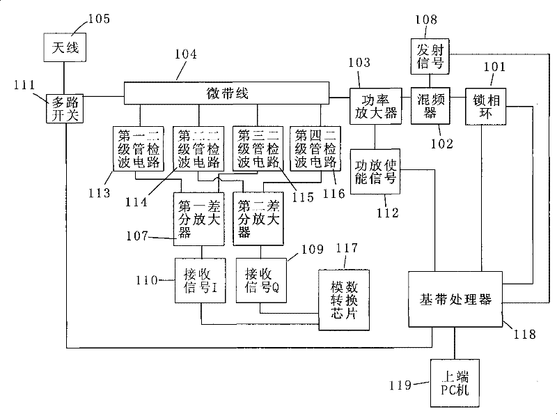
[0028] Embodiment 1, in the antenna channel detection circuit of the six-port circuit of the present invention, the phase-locked loop adopts the PLL400-915A of VARI-L, the output carrier frequency is 902MHz~928MHz, the mixer is selected HMC207S8, and the power amplifier is a metal oxide semiconductor field Effect transistor amplifier, the transmission on the microstrip line is the modulated signal amplified by the power amplifier after mixing, the multi-channel switch is a transceiver antenna switch SW425, which can connect two antennas, and the four-channel detection circuit is detected by zero-bias Schottky The differential amplifier is composed of two diodes, and the differential amplifier is composed of MAT04, which has four independent NPN transistors. The analog-to-digital conversion chip adopts AD7866. The baseband processor selects ADSP-BF537. The baseband control signal is a high and low level enable signal.

[0029] The working principle of the antenna channel dete...

Embodiment 2

[0035] Embodiment 2, using the circuit of Embodiment 1, the modulation information is 0xC0C0, the baud rate is 80Kbps, the carrier frequency is 915MHz, the threshold y1 is set to 1800, and the threshold y2 is set to 300. The RF output terminal is not connected to the load antenna. The upper-end PC sends an antenna detection command to the baseband processor to start the antenna detection process. The signal I and signal Q output by the first and second differential amplifiers collected by the analog-to-digital conversion chip are as follows: Figure 6-1 and Figure 6-2 shown. It can be clearly seen from the figure that when the modulated signal is transmitted, the signals I and Q are out of phase and the amplitudes are both greater than the threshold y1, while the peak-to-peak value of the signal I is greater than the set threshold y2 when the carrier is transmitted. It can be judged that the RF circuit is not connected to the load antenna.

Embodiment 3

[0036] Embodiment 3, using the circuit of Embodiment 1, the modulation information is 0xC0C0, the baud rate is 80Kbps, the carrier frequency is 915MHz, the threshold y1 is set to 1800, and the threshold y2 is set to 300. The RF output terminal is connected to the load antenna. The upper-end PC sends an antenna detection command to the baseband processor to start the antenna detection process. The signal I and signal Q output by the first and second differential amplifiers collected by the analog-to-digital conversion chip are as follows: Figure 7-1 and Figure 7-2 shown. It can be clearly seen from the figure that when the modulated signal is transmitted, the signals I and Q are in phase and the amplitudes are both greater than the threshold y1, while the peak-to-peak values ​​of the signal I and the signal Q are both smaller than the set threshold y2 when the carrier is transmitted. It can be judged that the radio frequency circuit is connected with a matching load antenn...


PUM


Abstract

The invention discloses an antenna channel testing method based on 6-port circuit, and the technical problem object to resolve is to simply, quickly and reliably judge the state of the electronic label read / write device antenna. The method of the invention includes the following steps: the baseband processor setting the carrier frequency output by the phase-locked loop, switching-on the power amplifier, starting up A / D conversion chip, sampling the signals, sending constant length of code to the frequency mixer; the detector diode circuit modulating signals from the micro-strip lines, sending to the baseband processor for processing after difference amplification and D / A conversion, so as to judge the antenna state. Compared with the prior technology, the baseband processor of the invention sets up the carrier frequency output by the phase-locked loop; the frequency mixer modulates a section of constant length code onto the carrier produced by the phase-locked loop and outputs after power amplification; the detector diode circuit checks out the modulating signals from the micro-strip lines, the modulating signals are formed into digit signals after amplification and D / A conversion, and then are sent to the baseband processor for processing to judge the antenna state, which is simple, quick and reliable.

Description

technical field [0001] The invention relates to a detection method of an antenna, in particular to a detection method of an antenna of an electronic tag reader-writer. Background technique [0002] The current UHF radio frequency identification air interface protocols include ISO18000-6B and EPC. These interface protocols all stipulate that the reader needs to continuously send carrier waves to provide energy to the electronic tag when receiving the information returned by the passive electronic tag. This working mode determines that the carrier must be transmitted simultaneously when measuring the received noise. The receiving noise of the radio frequency path determines the receiving sensitivity of the system, and this parameter determines the performance of the reader. [0003] The RF circuit system based on six ports has strict requirements on load matching. If the external antenna does not match the six-port network, the performance parameters of the entire system ma...

Claims


Application Information

Patent Timeline
Patent Type & Authority Patents(China)
IPC IPC(8): H04W24/00H04B17/00H04B17/309
Inventor 刘春江文艺清黄雪峰武岳山
Owner INVENGO INFORMATION TECH
Why Eureka
Try Eureka