Device for separating mud and water depending on high-frequency small-amplitude mechanical vibration

A technology of mud-water separation and mechanical vibration, which is applied in the direction of filtration separation, solid separation, sedimentation separation, etc., can solve the problems of different particle properties and cannot be applied to the use environment, etc., and achieve simple technical implementation, convenient operation and maintenance, and not easy to see plugs Effect

Inactive Publication Date: 2008-11-12
SHANGHAI JIAO TONG UNIV
View PDF1 Cites 16 Cited by
  • Summary
  • Abstract
  • Description
  • Claims
  • Application Information

AI Technical Summary

Problems solved by technology

Therefore, above-mentioned invention can not be applied to the mud-water separation that use environment, field are completely different, particle property is different

Method used


Image

  • Device for separating mud and water depending on high-frequency small-amplitude mechanical vibration
  • Device for separating mud and water depending on high-frequency small-amplitude mechanical vibration

Examples


Embodiment 1

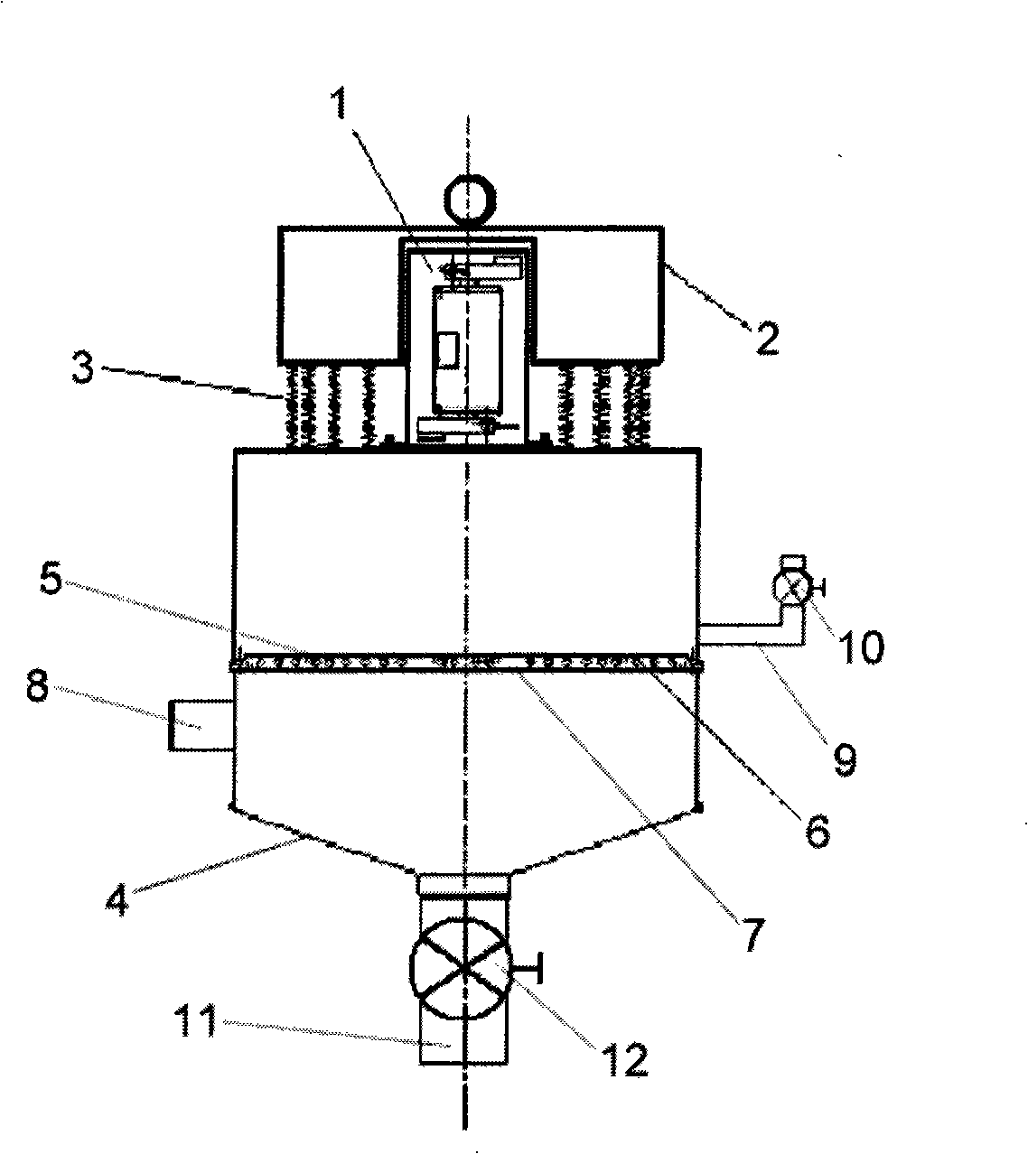
[0017] like figure 1 As shown, the present embodiment includes: a vibrating motor 1, a machine base 2, a spring 3, a mud-water separation chamber 4, a screen 5, a vibrating ball 6, a backing 7, an inlet pipe 8, an outlet pipe 9, an outlet pipe valve 10, an outlet pipe Mud pipe 11, mud pipe valve 12. The base 2 of the vibrating motor 1 is arranged on the mud-water separation chamber 4, the spring 3 connects the base 2 and the mud-water separation chamber 4, the screen 5 is arranged on the top of the vibrating ball 6, the bottom 7 is arranged on the middle part of the mud-water separation chamber 4, and the vibrating ball 6 is set between the screen 5 and the bottom 7, the water inlet pipe 8 is set on the mud-water separation chamber 4 and under the bottom 7; the outlet pipe 9 is set on the upper part of the mud-water separation chamber 4, and the outlet pipe valve 10 is set on the outlet pipe 9, the mud outlet pipe 11 is arranged at the bottom of the mud-water separation chamb...

Embodiment 2

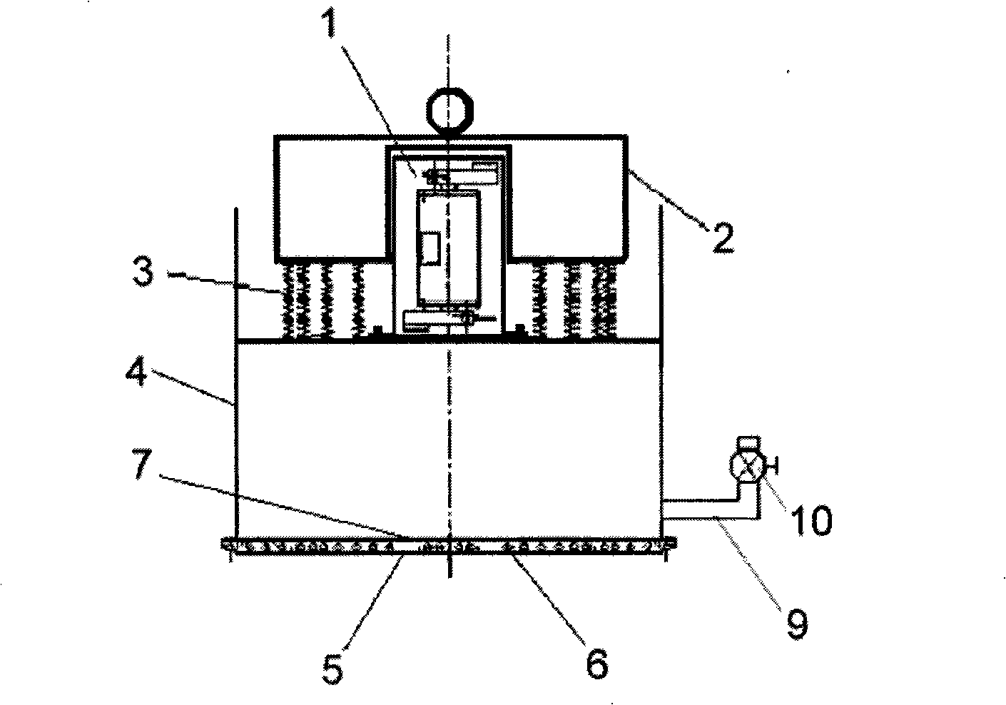
[0032] like figure 2 As shown, the present embodiment includes: a vibrating motor 1, a support 2, a spring 3, a mud-water separation chamber 4, a screen 5, a vibrating ball 6, a backing 7, an outlet pipe 9, and an outlet pipe valve 10. The base 2 of the vibrating motor 1 is arranged on the mud-water separation chamber 4 as a vibration source; the base 2 is installed on a support frame or a row frame. The spring 3 is arranged between the vibrating motor 1 and the mud-water separation chamber 4, and is connected by the spring 3, so that the part participating in the vibration becomes a complex three-dimensional movement in space; On the net 5, it is used to support the vibrating ball 6 and the screen 5, and is divided into several grids, and several vibrating balls 6 are placed in each grid; the vibrating ball 6 is arranged between the screen 5 and the bottom 7, and vibrates when working. The ball 6 continuously vibrates and hits the screen 5 to achieve the effect of clearing ...

Embodiment 3

[0035] This embodiment includes: vibrating motor 1, machine base 2, spring 3, mud-water separation chamber 4, screen 5, vibrating ball 6, bottom support 7, water inlet pipe 8, water outlet pipe 9, water outlet pipe valve 10, mud outlet pipe 11 , mud pipe valve 12. The vibrating motor 1 is arranged on the mud-water separation chamber 4, and the mud-water separation chamber 4 is cylindrical, with a height of 1.5 meters and a section diameter of 1 meter. The vibration frequency of the vibration motor 1 is 7200 times / minute, the maximum amplitude is 5mm, and the power is 1.5 kilowatts. The spring 3 made of stainless steel connects the support 2 and the mud-water separation chamber 4. The screen cloth 5 is arranged on the vibrating ball 6 top, and the bottom 7 is arranged at a height of 0.5 meters from the top of the mud-water separation chamber 4 . The screen 5 is woven by stainless steel wire, and the mesh size is 40 microns. The vibrating ball 6 is arranged between the screen...


PUM

PropertyMeasurementUnit
diameteraaaaaaaaaa
diameteraaaaaaaaaa

Abstract

The invention provides a mud water separation device which mechanically vibrates with small amplitude by high frequency, belonging to the technical field of hydraulic engineering; wherein, the frame of a vibration motor is arranged on a mud water separation chamber and taken as a vibration source; a spring is arranged and connected between the vibration motor and the mud water separation chamber; a bracket is arranged in the mud water separation chamber and used for supporting a vibration ball and a screen; the bracket is divided into a plurality of grids; each grid is internally provided with a plurality of vibration balls which are arranged between the screen and the bracket; the screen is arranged on the vibration ball; a water inlet pipe is arranged on the mud water separation chamber and lower than the bracket; the water outlet pipe is arranged on the mud water separation chamber and higher than the bracket; a water outlet pipe is provided with a water outlet pipe valve; a mud outlet pipe is arranged at the bottom of the mud water separation chamber and provided with a mud outlet pipe valve; alternatively, the mud water separation device of the invention can save the water inlet pipe, the mud outlet pipe and the mud outlet pipe valve. The mud water separation device can separate the mud sand grain from water flow with high efficiency, improves the productivity of the dredge and water disposal industry, and reduces the industrial energy loss.

Description

technical field [0001] The invention relates to a separation device in the technical field of water conservancy engineering, in particular to a mud-water separation device relying on high-frequency micro-amplitude mechanical vibration. Background technique [0002] Land reclamation and port channel maintenance often encounter dredging problems. In order to increase the loading capacity of dredgers and the concentration of sediment transported by pipelines, part of the water needs to be removed from the mud. In addition, in the field of water treatment, it is necessary to separate the sediment particles from the muddy water to improve the water quality of the water body. The dredging industry and water treatment industry urgently need to develop new mud-water separation devices. [0003] Found through the retrieval of prior art document, at present the most closely with the present invention is application (patent) number: 200580038239.7, name: be used for separating the dev...

Claims


Application Information

Patent Timeline
Patent Type & Authority Applications(China)
IPC IPC(8): B07B1/40B01D35/20B01D21/28C02F11/12
Inventor 喻国良
Owner SHANGHAI JIAO TONG UNIV
Why Eureka
Try Eureka