Water jet cutting system

A cutting system and water jet technology, applied in abrasive jet machine tools, explosion generating devices, abrasives, etc., can solve the problems of high acceleration and deceleration, increased space occupied, inability to provide, etc., and achieve the effect of reducing pressure and increasing life.

Inactive Publication Date: 2008-11-12
FLOW ASIA CORP
View PDF0 Cites 11 Cited by
  • Summary
  • Abstract
  • Description
  • Claims
  • Application Information

AI Technical Summary

Problems solved by technology

Therefore, for the water jet cutting system whose driving structure is cantilever type and driven by screw, it cannot provide high acceleration and deceleration. If it is applied to cutting small-sized semiconductor components, during the cutting process, it will Waste a lot of time accelerating and decelerating
Therefore, if the water jet cutting system with cantilever driving structure is applied to cutting small-sized semiconductor components, the cutting output will be directly limited due to the above reasons, and it may also cause cutting failure due to the small size of the material result
In addition, the water jet cutting system with the cantilever drive structure is bulky and takes up a relatively large space

Method used


Image

  • Water jet cutting system
  • Water jet cutting system
  • Water jet cutting system

Examples


Embodiment Construction

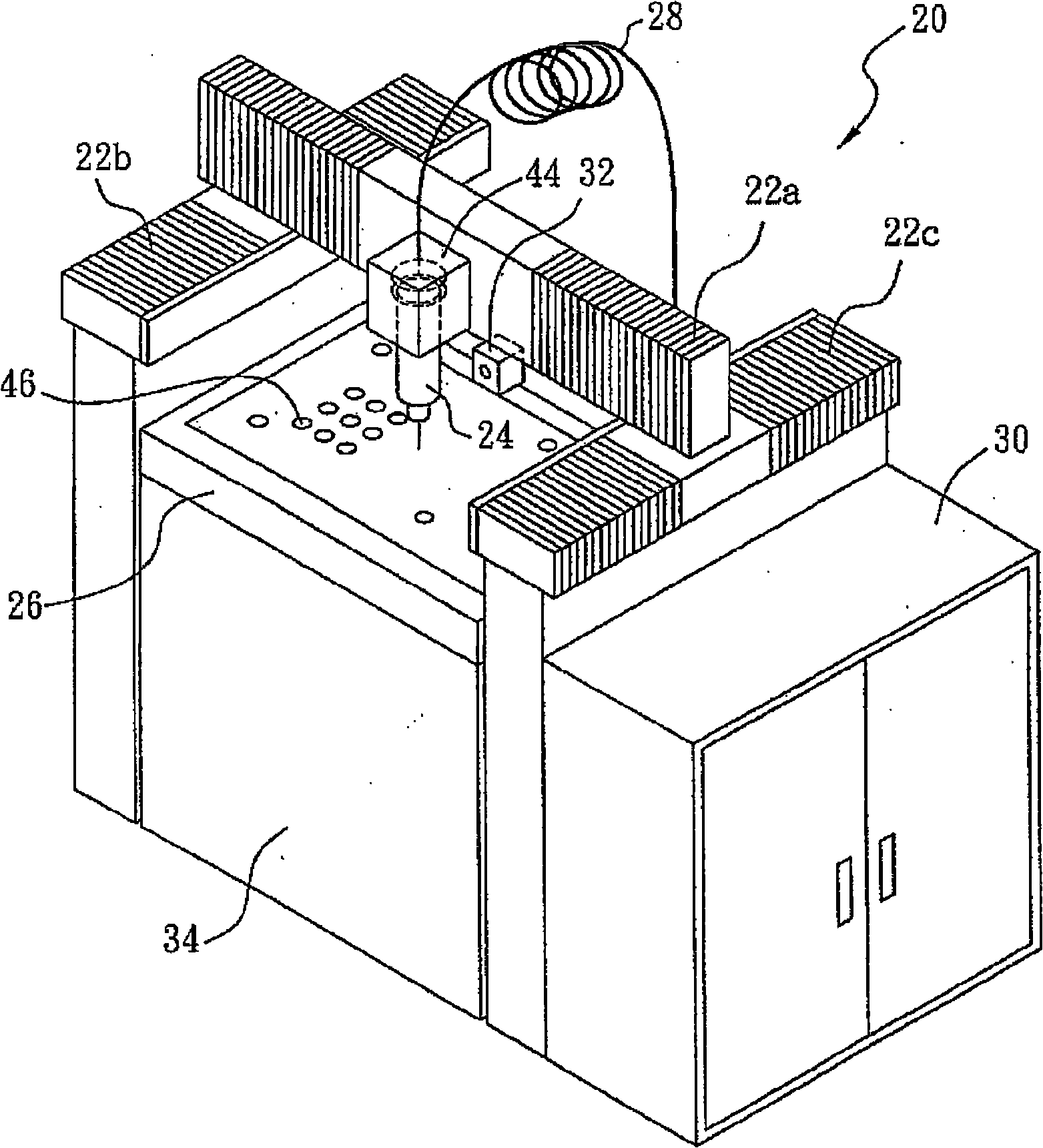
[0019] Such as figure 2 As shown, the water jet cutting system ( 20 ) according to the first embodiment of the present invention includes: a gate type driving device ( 22 ), a high-voltage generating device (not shown) and a cutting device ( 24 ). The water jet cutting system is used to cut semiconductor components, wherein the gate drive device is used to provide driving force in the x-y plane; the high-pressure generating device is used to generate high-pressure water flow; and the cutting device is coupled to the high-voltage A generating device and the door-type driving device are used to cut the semiconductor element by using the high-pressure water flow under the driving of the door-type driving device.

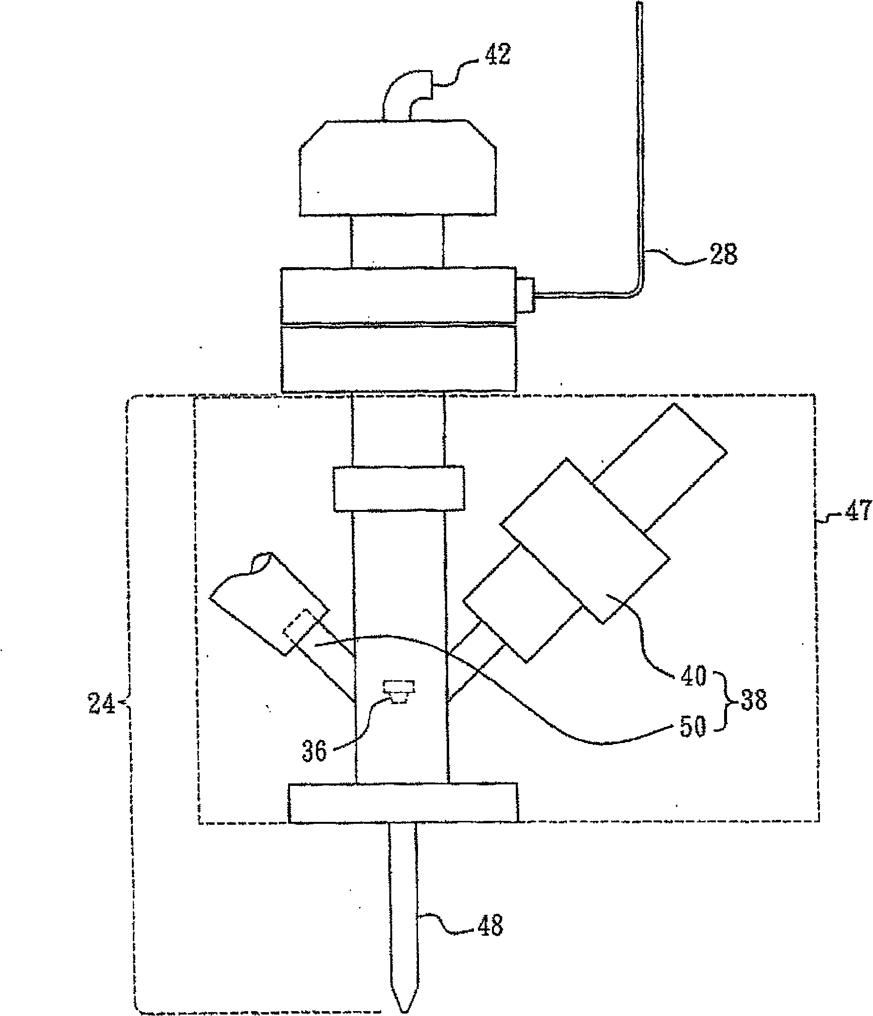
[0020] According to the water jet cutting system (20) of another embodiment of the present invention, because the speed of the high-pressure water flowing through the high-pressure generating device is very fast, the present invention designs the high-pressure pipe (28...


PUM


Abstract

The invention relates to a water jet cutting system used for cutting semiconductor elements, comprising a gantry driving device used for providing the driving force of x-y plane, a high pressure generation device used for generating high pressure water jet and a cutting device which is coupled to the high pressure generation device and the gantry driving device; the semiconductor element is cut by the high pressure water jet under the driving of the gantry driving device.

Description

technical field [0001] The present invention relates to a water jet cutting system, and in particular to a water jet cutting system for cutting semiconductor components. Background technique [0002] The cutting technology of conventional semiconductor elements is based on a dicing saw (Dicing Saw). The cutting technology mainly performs linear cutting, and it is difficult to cut materials into non-linear shapes. However, for some semiconductor components, not only a very small size is required, but also components with non-linear edges must be cut sometimes. In this case, the difficulty and failure rate of traditional cutting will inevitably increase. In addition, such conventional cutting techniques will generate heat energy during cutting. For some semiconductor elements (such as: flash memory) formed of materials such as plastics and metals or having a stacked structure, if this cutting technique is used, The thermal effect generated in the cutting process will lead to ...

Claims


Application Information

Patent Timeline
Patent Type & Authority Applications(China)
IPC IPC(8): B24C1/00B24C3/32B24C5/02
Inventor 方赞候
Owner FLOW ASIA CORP
Why Eureka
Try Eureka