
Method for manufacturing semiconductor device

A manufacturing method and semiconductor technology, which are applied in semiconductor/solid-state device manufacturing, semiconductor devices, electric solid-state devices, etc., can solve problems such as affecting the stability of the package block, affecting the packaging process, and poor adhesion of the pad 18a.

Inactive Publication Date: 2008-11-12
SEMICON MFG INT (SHANGHAI) CORP
View PDF1 Cites 21 Cited by
  • Summary
  • Abstract
  • Description
  • Claims
  • Application Information

AI Technical Summary

Problems solved by technology

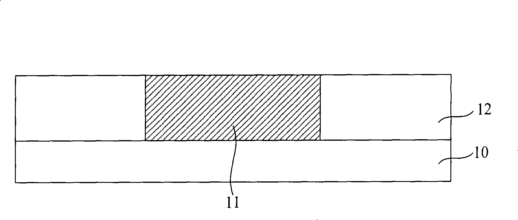
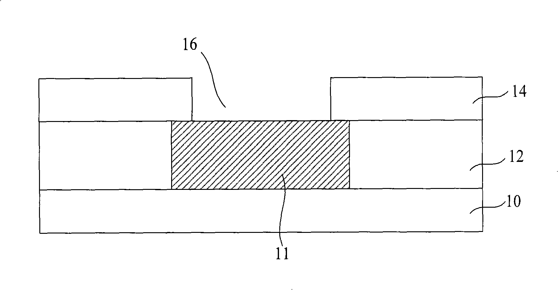
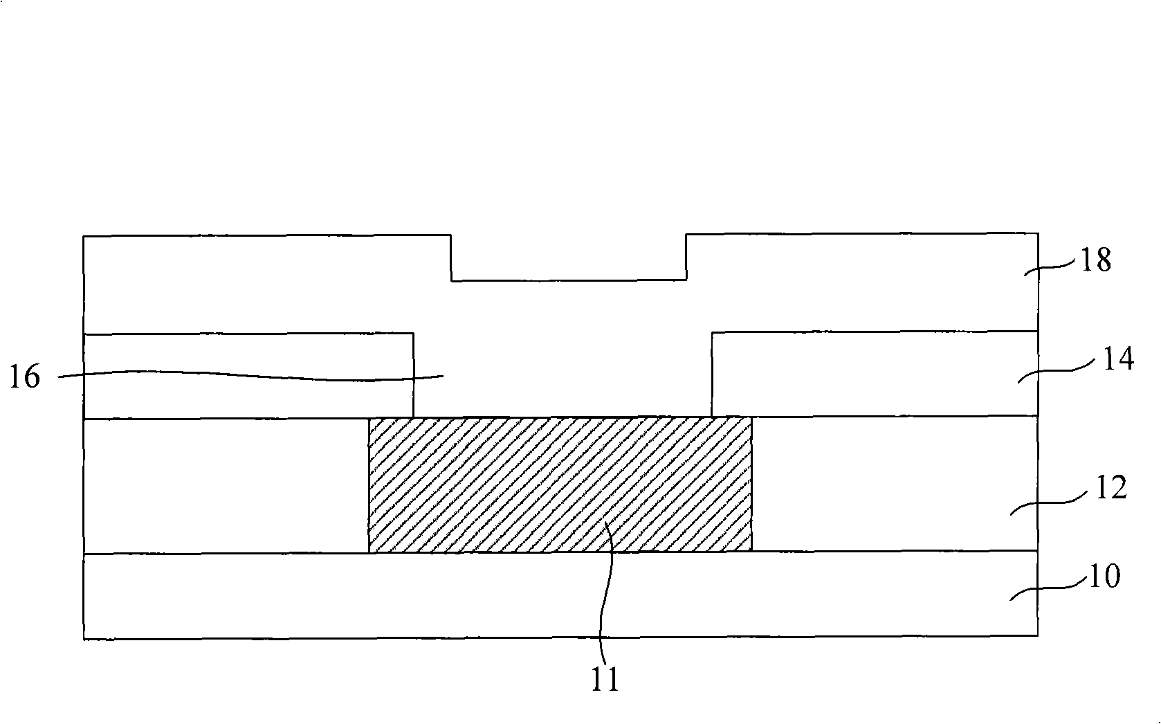
[0010] In the above manufacturing process, the second opening 17 is generally formed by plasma dry etching the passivation layer 20, and the etching gas is a gas containing fluorine; during the etching process, such as Figure 7 The polymer 21 shown, the polymer 21 is attached to the sidewall of the second opening 17; in the subsequent package process, it is necessary to form external leads or solder on the solder pad 18a at the bottom of the second opening 17 Bumps, the polymer 21 will affect the subsequent packaging process, so that the adhesion of solder bumps or outer leads to the solder pads 18a becomes poor; thus affecting the stability of the formed packaging block

Method used


Image

  • Method for manufacturing semiconductor device
  • Method for manufacturing semiconductor device
  • Method for manufacturing semiconductor device

Examples


Embodiment Construction

[0038] The specific embodiments of the present invention will be described in detail below in conjunction with the accompanying drawings.

[0039] Figure 8 It is a flow chart of an embodiment of the manufacturing method of the semiconductor device of the present invention. Figures 9 to 19 The figure is a schematic cross-sectional view of the structure corresponding to each step of the embodiment of the manufacturing method of the semiconductor device of the present invention.

[0040] Such as Figure 8 The flow chart shown, step S100 , provides a semiconductor structure with an aluminum pad on the semiconductor structure and a passivation layer on the semiconductor structure and the aluminum pad.

[0041] Such as Figure 9 The cross-sectional schematic diagram shown provides a semiconductor structure, which includes a semiconductor substrate 30 and a dielectric layer 32 on the semiconductor substrate 30 , and a metal interconnection line 31 is provided in the dielectric l...


PUM


Abstract

The invention relates to a manufacturing method for a semiconductor device, which provides a semiconductor structure. The semiconductor structure is provided with an aluminum welding pad; a passivation layer is arranged on the semiconductor structure and the aluminum welding pad; a photo resist layer is formed on the passivation layer and is schematized to form an opening pattern; the passivation layer on the bottom of the opening pattern is etched and an opening is formed in the passivation layer; the photo resist layer is removed; the bottom and side walls of the opening are washed by aqueous solution containing sulphuric acid and oxyful; the bottom and side walls of the opening are further washed by aqueous solution containing hydrofluoric acid and ammonia. The method can eliminate polymers generated in the process of etching the passivation layer.

Description

technical field [0001] The invention relates to the technical field of semiconductor manufacturing, in particular to a manufacturing method of a semiconductor device. Background technique [0002] In the semiconductor manufacturing process, after completing the manufacturing process of the semiconductor device in the front section and the metal interconnection line in the back section, it is necessary to form a pad on the top layer metal interconnection line; in the packaging process, the outer lead is directly welded on the Solder bumps are formed on or on the pads. Aluminum metal has the advantages of low resistivity, easy etching, and good bonding characteristics with dielectric materials and metal materials, and is often used to manufacture solder pads. Due to the simple aluminum process and low cost, aluminum metal is often used to make welding pads in the process of 65nm or even smaller technology nodes. [0003] Figure 1 to Figure 6 It is a schematic cross-sectiona...

Claims


Application Information

Patent Timeline
IPC IPC(8): H01L21/60H01L21/3105H01L21/311H01L21/3213
CPCH01L24/05H01L2224/02166H01L2224/05624
Inventor 沈满华张世谋王新鹏孙武
Owner SEMICON MFG INT (SHANGHAI) CORP
Learn More