Two stage hot pipe EGR cooler

A technology of EGR cooler and heat pipe, which is applied in machines/engines, adding non-fuel substances to fuel, internal combustion piston engines, etc., can solve the problem of reducing the cooling efficiency of EGR cooler, cavitation of engine cooling circuit, reducing the degree of vaporization of coolant, etc. problems, to achieve the effect of strong horizontal free scalability, reduce impact, and improve cooling effect

Active Publication Date: 2008-11-19
ZHEJIANG YINLUN MACHINERY
View PDF0 Cites 4 Cited by
  • Summary
  • Abstract
  • Description
  • Claims
  • Application Information

AI Technical Summary

Problems solved by technology

They mainly have the following disadvantages: 1. The traditional exhaust gas cooling method uses engine coolant for cooling. Since the coolant in the steam state will cause serious cavitation to the engine cooling circuit, the engine coolant always exists in liquid form under working conditions. That is to say, the cooling of the exhaust gas is carried away by the temperature rise of the engine coolant, which has a poor cooling effect.
2. The conventional EGR cooler adopts shell-and-tube or plate-fin structure, and the compact structure is easier to carbonize, which will greatly reduce the cooling efficiency of the EGR cooler
3. In the traditional shell-and-tube EGR cooler, the weld between the tube bundle and the end plates on both sides is obviously affected by thermal stress and is easy to leak
4. In the traditional shell-and-tube EGR cooler, the flow direction of the exhaust gas is the same as that of the coolant. The purpose is to reduce the degree of vaporization of the coolant, but the cooling effect of the forward flow is not as good as that of the reverse flow.

Method used


Image

  • Two stage hot pipe EGR cooler
  • Two stage hot pipe EGR cooler
  • Two stage hot pipe EGR cooler

Examples


Embodiment Construction

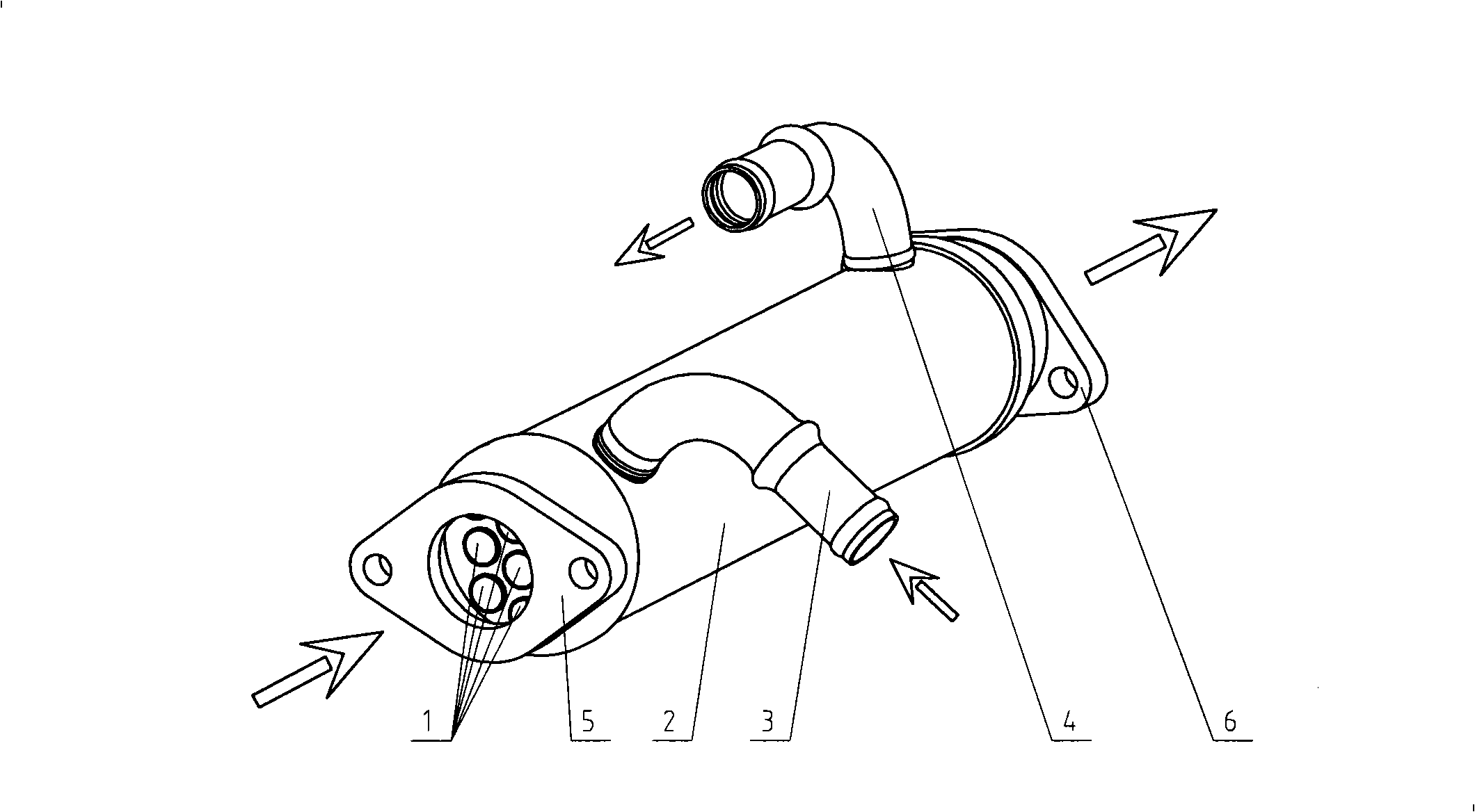
[0019] refer to figure 1 , this figure shows a traditional shell-and-tube EGR cooler, which includes a casing 2 with a coolant inlet 3 and an outlet 4 on the side, and a set of replacement parts arranged in parallel in the casing 2 with gaps between them. heat pipe1. The heat exchange tube 1 is connected to the exhaust gas recirculation circuit of the engine through an inlet flange 5 and an outlet flange 6 . And the engine coolant enters the inner cavity of the housing 2 from the coolant inlet 3 after being drawn out from the pipeline, then flows out from the coolant outlet 4, and is sent back to the engine cooling system by the pipeline. In this structure, in order to achieve a better heat exchange effect, the heat exchange tubes 1 are generally many and very thin. In the narrow pipes in the heat exchange tubes, the inner wall of the tubes is easy to be carbonized, and the carbonization is difficult to remove automatically, greatly Reduced cooling efficiency of the EGR cool...


PUM


Abstract

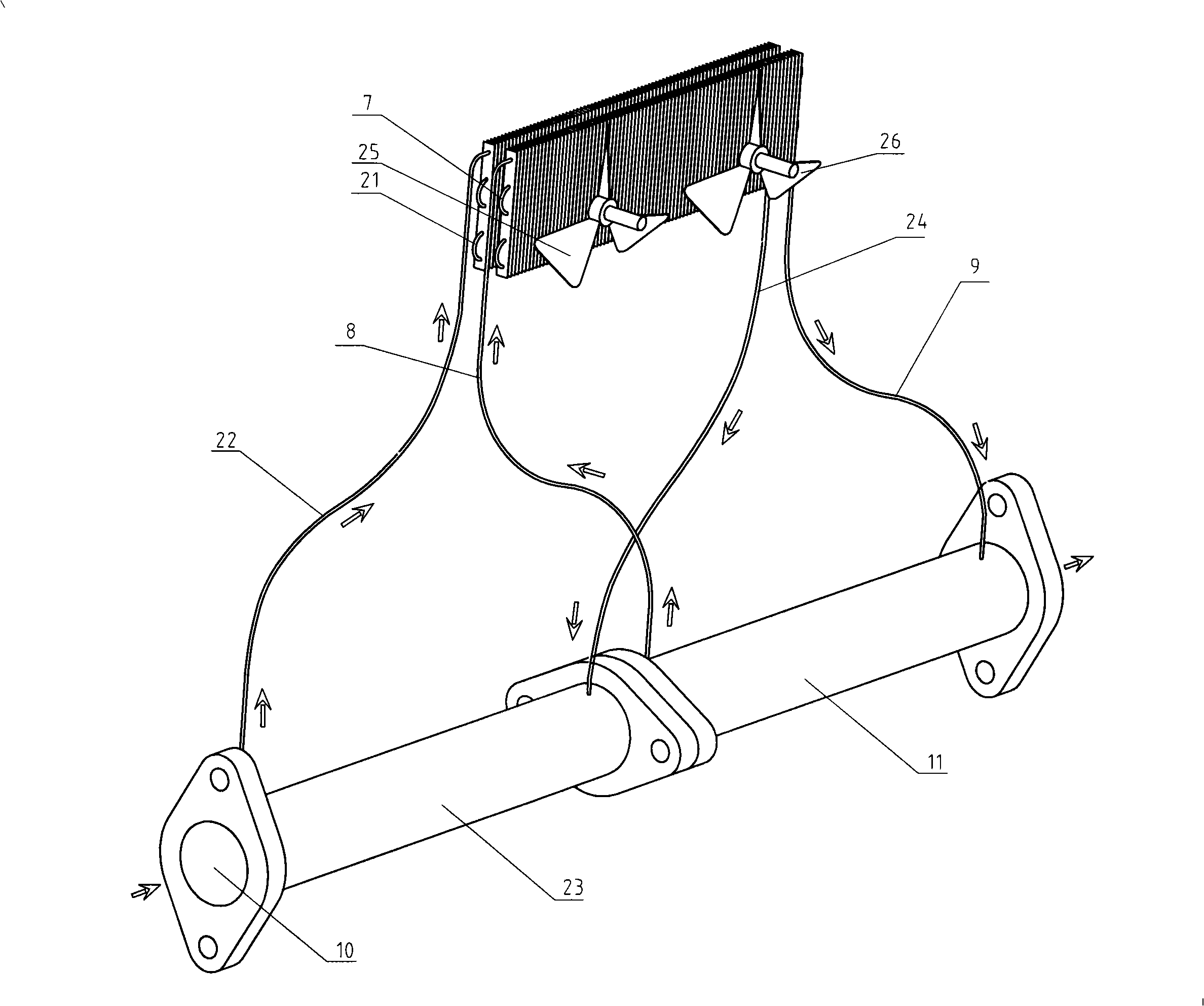
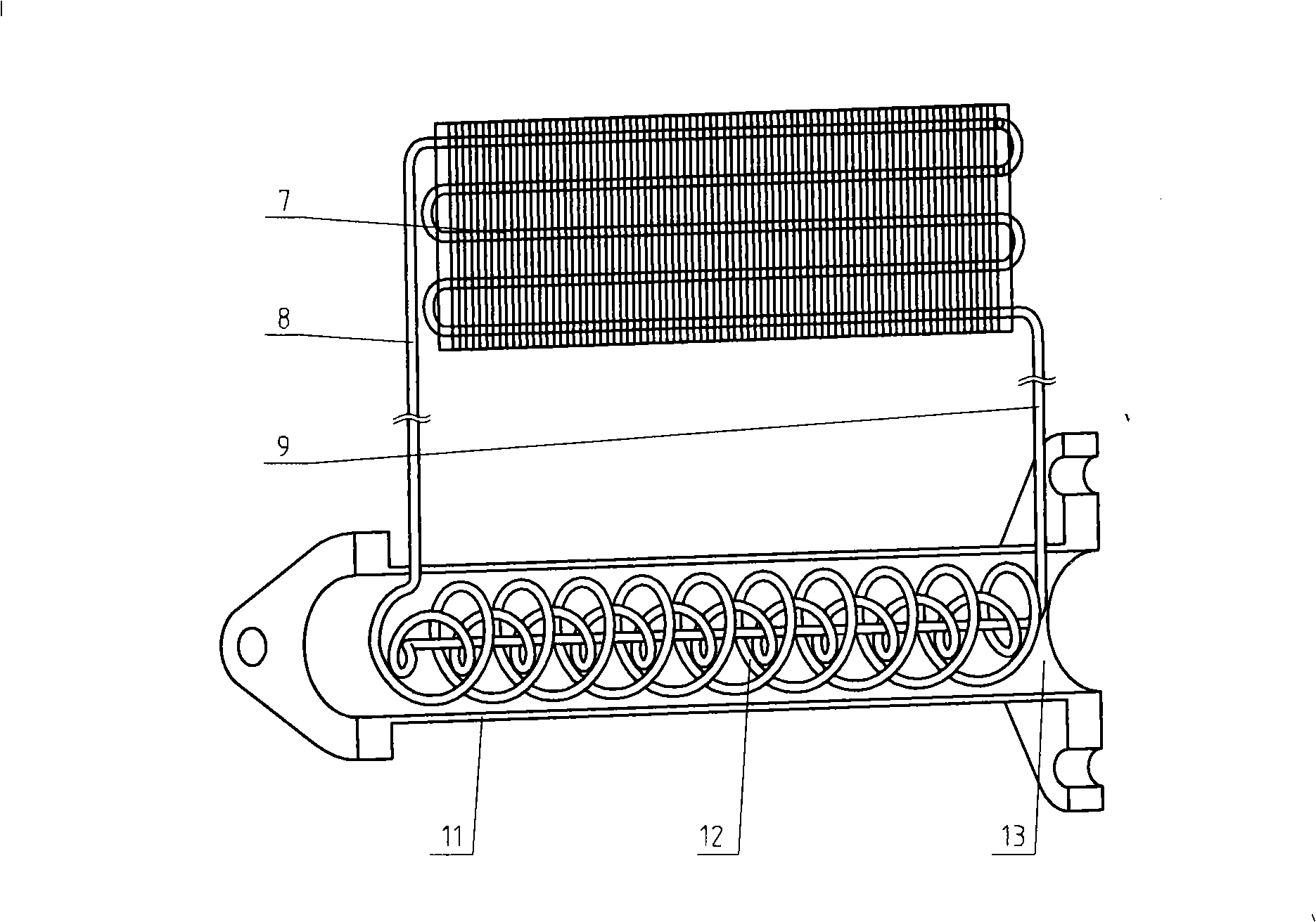
The invention discloses a two-stage thermotube type EGR cooler. The two-stage thermotube type EGR cooler mainly consists of a shell with an exhaust gas inlet and an exhaust gas outlet respectively arranged on two ends of the cooler and a two-stage thermotube with heating sections arranged inside the shell. The thermotube is communicated with four pipe sections of a heating section, a steam tube, a condensation section and a condensation tube in turn from beginning to end; the heating sections of the two-stage thermotube are arranged along the exhaust gas flow direction in order; and the condensation sections of the two-stage thermotube are overlapped and arranged along the radiation wind blowing direction. In the two-stage thermotube, a first stage thermotube and a second stage thermotube respectively adopt water and methanol as cooling mediums. The two-stage thermotube type EGR cooler adopts the principle of cooling exhaust gas by the thermotube technology and has good cooling effect. In addition, the reasonable combination of the two-stage thermotube and the cross matching of two radiating mediums further improve the temperature reduction effect of the cooler.

Description

technical field [0001] The invention relates to a gas cooling device, in particular to an exhaust gas recirculation cooler. It can be widely used in power plants using exhaust gas recirculation. Background technique [0002] With the increasingly stringent emission requirements, exhaust gas recirculation technology is increasingly used in power plants. The principle is to cool part of the exhaust gas discharged for the first time and then return it to the engine to effectively reduce the formation of nitrogen oxides in the exhaust gas. The coolers in the traditional exhaust gas recirculation (EGR) process are roughly divided into two types: shell-and-tube type and plate-fin type. They mainly have the following disadvantages: 1. The traditional exhaust gas cooling method uses engine coolant for cooling. Since the coolant in the steam state will cause serious cavitation to the engine cooling circuit, the engine coolant always exists in liquid form under working conditions. ...

Claims


Application Information

Patent Timeline
Patent Type & Authority Applications(China)
IPC IPC(8): F02M25/07F02M26/29
CPCY02T10/121Y02T10/12
Inventor 陆国栋安晓平张首都叶万鑫褚礼亚
Owner ZHEJIANG YINLUN MACHINERY
Why Eureka
Try Eureka