Ac motor

An AC motor, alternate ground technology, applied in the direction of electric components, electrical components, electromechanical devices, etc., can solve the problems of difficult to form magnetic cores, expensive, poor magnetism and strength, and achieve the effect of improving productivity

Inactive Publication Date: 2008-11-26
DENSO CORP
View PDF2 Cites 7 Cited by
  • Summary
  • Abstract
  • Description
  • Claims
  • Application Information

AI Technical Summary

Problems solved by technology

[0010] However, the AC motor disclosed in Patent Document 2 has a problem that since magnetic flux flows three-dimensionally in the motor, it is difficult to form its magnetic core by laminating electrical steel sheets because the magnetic anisotropy of the magnetic core
Although, powder cores (powder cores) are known as magnetic cores without magnetic anisotropy, they are expensive and inferior in magnetic properties and strength to cores formed by laminating electrical steel sheets (electrical steel sheets)

Method used


Image

  • Ac motor
  • Ac motor
  • Ac motor

Examples


Embodiment Construction

[0056] Embodiments of the AC motor of the present invention will be described below.

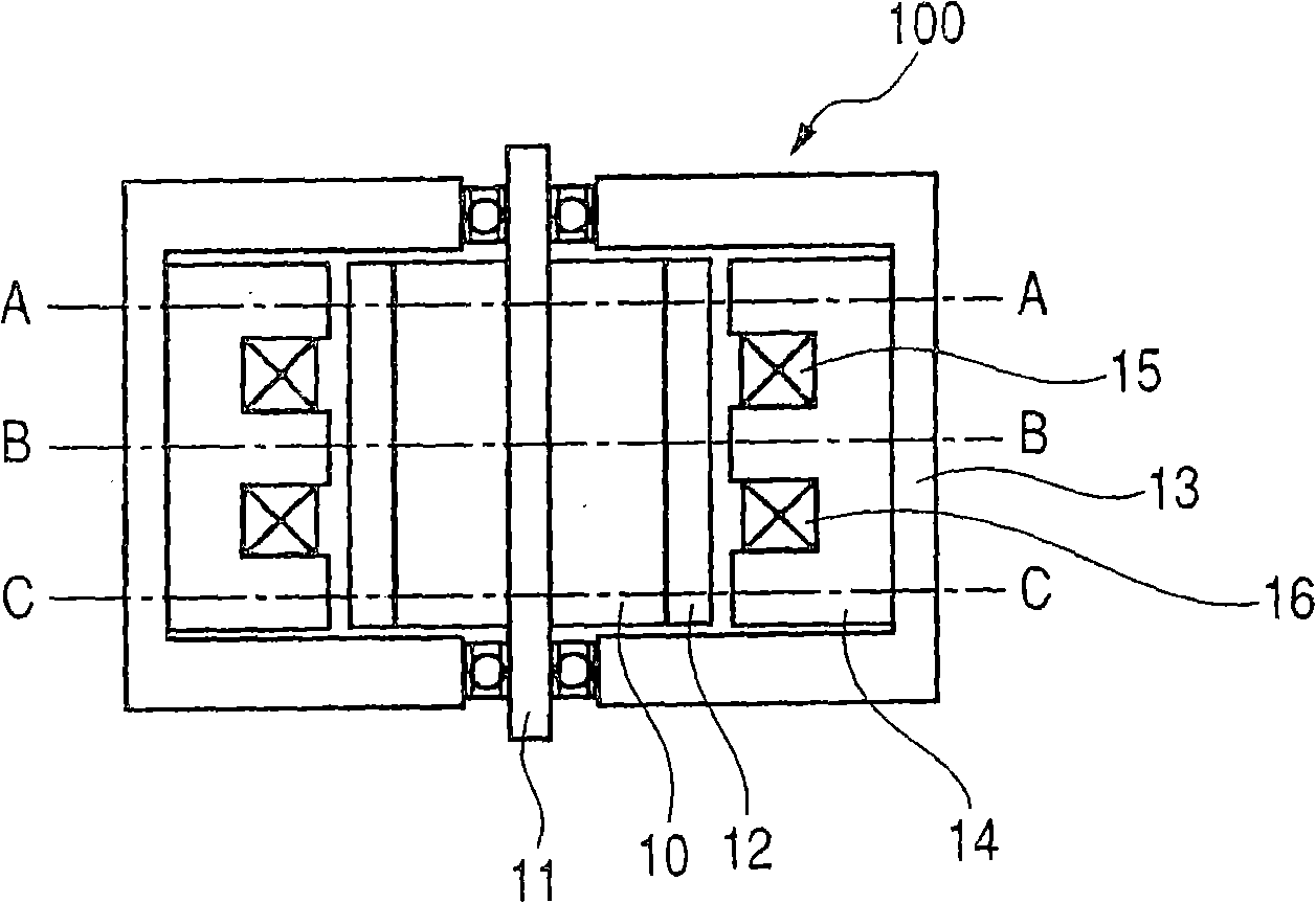
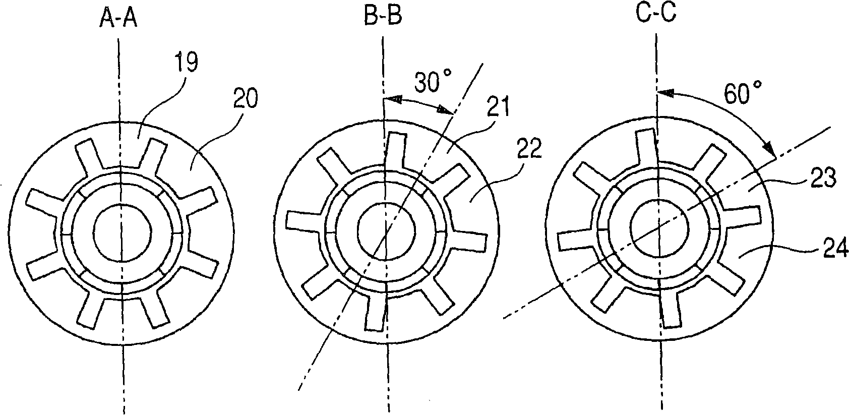
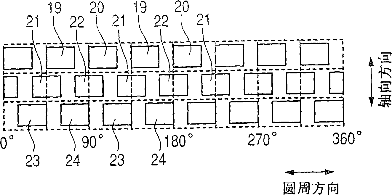
[0057] figure 1 is a schematic axial sectional view of the motor 100 . figure 2 is the display edge figure 1 A-A, B-B, C-C are schematic cross-sectional views of the motor 100 . image 3 is a schematic diagram of the circumferential development of the stator poles of the motor 100 . Figure 4 is a schematic diagram of the circumferential development of the rotor of the motor 100 . Figure 5 It is a schematic diagram of the circular expansion of the ring winding (two phase windings of different phases) of the motor 100 .

[0058] First, the basic structure of the motor 100 will be described.

[0059] The motor 100 includes a rotor 10 fixed to a rotating shaft 11 and having an SPM (surface permanent magnet) structure in which a cylindrical permanent magnet 12 is fixed to the outer periphery of the rotor 10 . The rotary shaft 11 is rotatably supported by the housing 13 through bearings...


PUM


Abstract

The motor includes a rotor including N-pole magnets and S-pole magnets located alternately along a circumferential direction of said AC motor, a stator core including a plurality of partial cores arranged coaxially along an axial direction of said AC motor each of said partial cores including a plurality of stator poles located along said circumferential direction so as to be on the same circumference, and a plurality of loop-like windings each of which extends in said circumferential direction while passing through, in said axial direction, interpole spaces between each two adjacent stator poles in said circumferential direction. The a phase angle difference between each adjacent two of said stator poles in said circumferential direction of the same one of said partial cores is set at a value smaller than 360 degrees for each of said partial cores.

Description

technical field [0001] The present invention relates to an AC motor, in particular to an AC motor with a structure in which the magnetic poles of the stator are positioned along the axial direction of the AC motor. Background technique [0002] Figure 25-27 There is shown a concentrated winding motor disclosed in Japanese Patent Application Laid-Open Publication No. 6-261513 (Patent Document 1), which has a coil in which each phase coil is concentratedly wound on a corresponding stator pole. structure. Figure 25 is a schematic axial sectional view of the motor, Figure 26 is a schematic circular cross-sectional view of the motor, Figure 27 is a schematic diagram of the circumferential development of the stator of the motor. [0003] The conventional concentrated winding motor disclosed in Patent Document 1 has a problem that the structure is complicated because each winding must be wound around each stator pole. In addition, since the winding must be located at the bo...

Claims


Application Information

Patent Timeline
Patent Type & Authority Applications(China)
IPC IPC(8): H02K1/27H02K1/12H02K3/04H02K21/12H02K29/00
CPCH02K2201/06H02K21/16H02K29/03
Inventor 牧田真治梨木政行镰田义信高桥英介
Owner DENSO CORP
Why Eureka
Try Eureka