High power LED phase transition heat sink structure

A high-power, phase-change heat technology, applied to semiconductor/solid-state device parts, semiconductor devices, electrical components, etc., can solve problems such as heat dissipation, achieve the effect of improving heat dissipation, reducing temperature difference, and expanding the scope of application

Inactive Publication Date: 2008-12-03
SOUTH CHINA UNIV OF TECH
View PDF0 Cites 25 Cited by
  • Summary
  • Abstract
  • Description
  • Claims
  • Application Information

AI Technical Summary

Problems solved by technology

When multiple LEDs are densely arranged to form a white light lighting system, the problem of heat dissipation is more serious

Method used


Image

  • High power LED phase transition heat sink structure
  • High power LED phase transition heat sink structure
  • High power LED phase transition heat sink structure

Examples


Embodiment 1

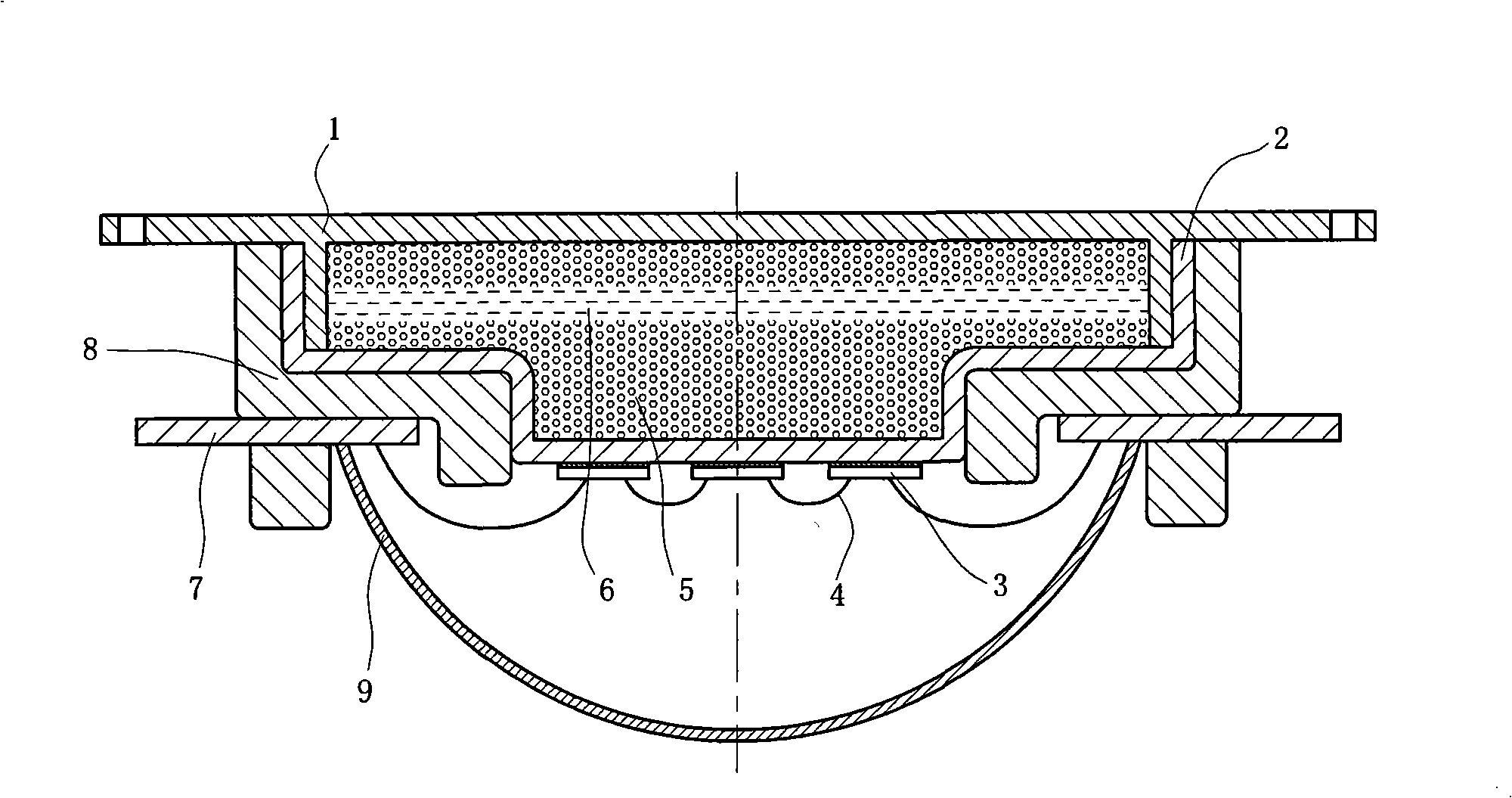
[0028] Such as figure 1 , 2 As shown, the phase change heat sink and packaging structure of a high-power LED includes a sealing end cover 1, a heat sink body 2, a high-power LED chip 3, a gold wire 4, a boiling structure 5, a working medium 6, and an electrode 7 And the lens 9, the sealing end cap and the heat sink body are circular structures with cavities, which are closely connected by welding or cementing to form a closed cavity, which is sealed into a vacuum state, and has a boiling structure 5 and low temperature in the cavity. Boiling heat transfer working medium 6; the sealing end cover 1 and the LED mounting aluminum substrate can be connected together by screws; the outside of the lower end of the heat sink body 2 and the outside of the sealing end cover 1 are both planar structures. The boiling structure 5 is in the form of copper powder sintering. First put the copper powder into the cavity of the sealing end cover 1 and the heat sink body 2, reserve 10% of the ca...

Embodiment 2

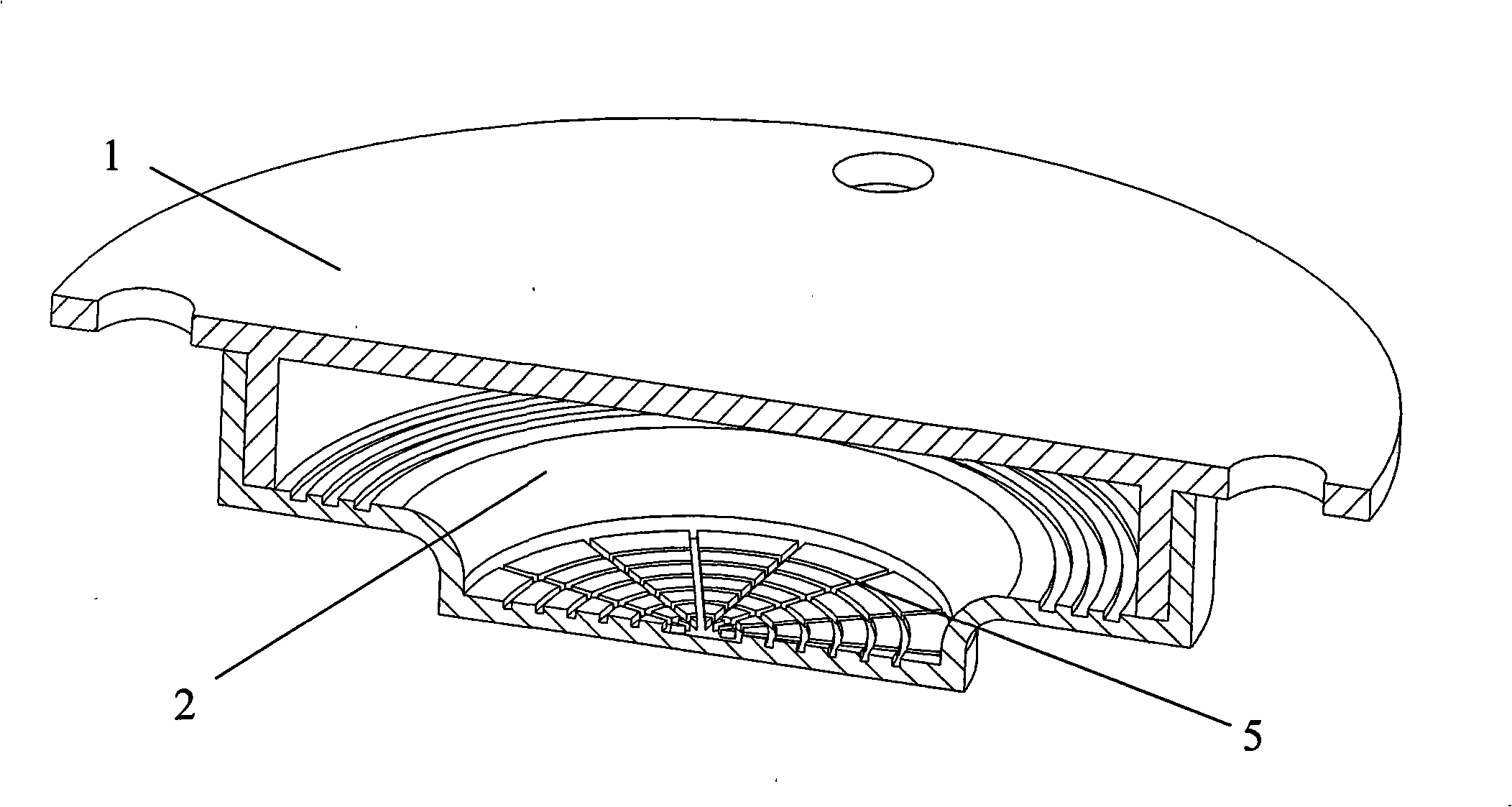
[0030] Such as image 3 As shown, a high-power LED phase-change heat sink and sealing end cap 1 of the packaging structure adopts a circular structure, is placed in the heat sink body 2, and is connected with the heat sink body 2 by welding or gluing. The heat sink body 2 and the LED mounting aluminum substrate can be connected together by screws; the lower end of the heat sink body 2 adopts a circular structure, and the boiling structure 5 is made of porous material sintered. The porous material is commercial foam copper or aluminum foam. The sintering method Same as copper powder sintering. The low temperature boiling heat transfer working medium 6 is acetone. Such as Figure 5b As shown, the high-power LED chips 3 are arranged in a circle, and are fixed on the lower end of the heat sink body 2 by welding in parallel or in series. Others are with embodiment 1.

Embodiment 3

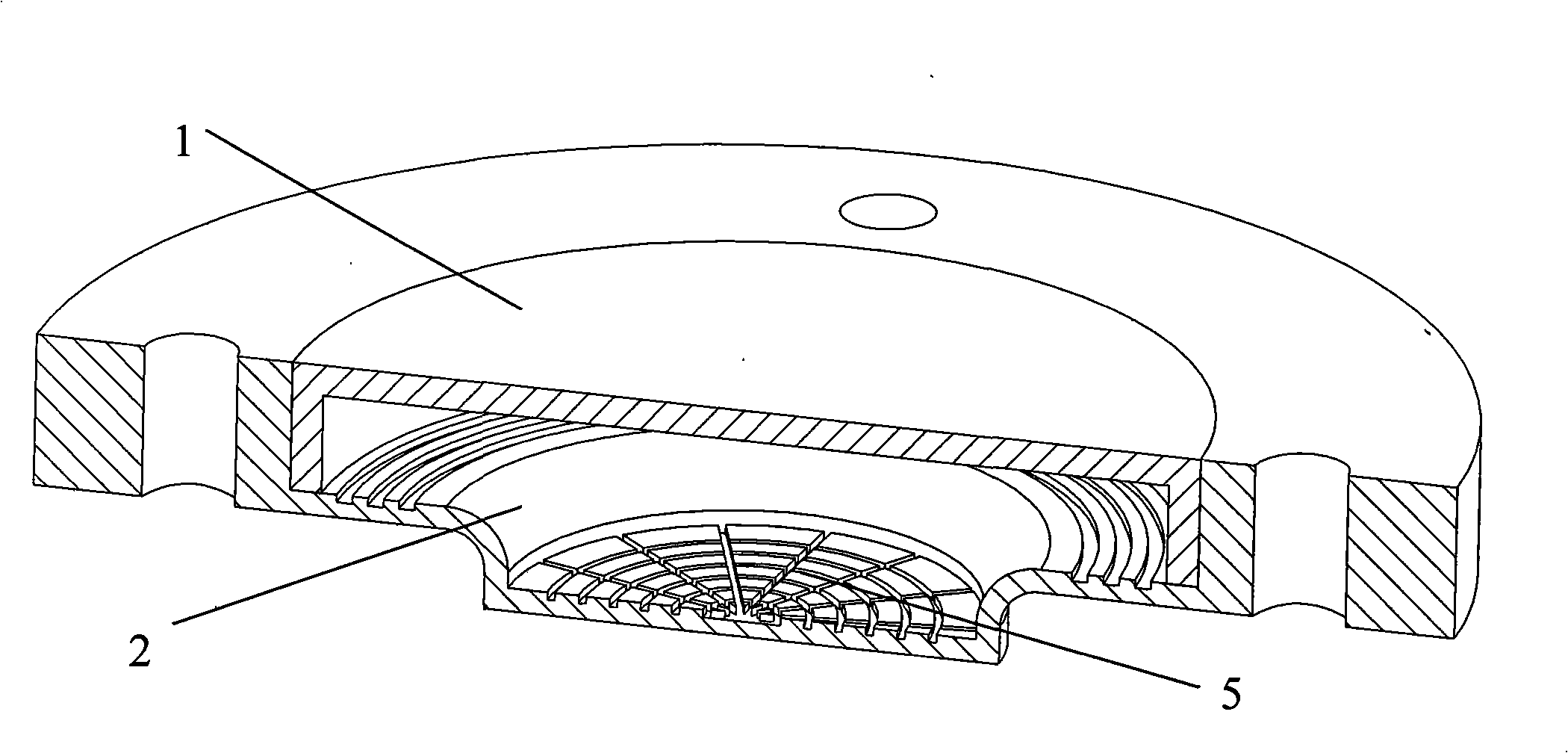
[0032] Such as Figure 4 As shown, a high-power LED phase-change heat sink and sealing end cap 1 of the packaging structure adopts a square structure, is placed in the heat sink body 2, and is connected with the heat sink body 2 by welding or bonding, and the heat sink body 2 is connected together. The sink body 2 and the LED mounting aluminum substrate can be connected together by screws; the lower end of the heat sink body 2 adopts a square structure, and the boiling structure is in the form of square grooves, and the grooves are processed by ordinary machine tools at the lower end of the cavity. The high-power LED chip 3 is one piece, which is fixed on the lower end of the heat sink body 2 by welding, and the low-temperature boiling heat transfer medium 6 is ethanol; the others are the same as in the first embodiment.


PUM


Abstract

The invention discloses a high-power LED phase-change heat sink structure, the heat sink body of the structure is a circular or square structure with an cavity, a boiling structure and a low temperature boiling heat transfer working medium are arranged in the cavity, a sealing end cover is arranged at the upper end of the heat sink body and tightly connected with the heat sink body, thus forming the closed cavity, the inner surface of the sealing end cover is a condensation structure, and the cavity is sealed into the vacuum state; at least one high-power LED chip is fixed at the lower end of the outside of the heat sink body, an electrode is arranged outside of the phase-change heat sink, the phase-change heat sink, the electrode and a lens are connected by packaging resin, and the high-power LED chip is directly connected with the electrode by a gold wire. The high-power LED phase-change heat sink structure utilizes the liquid-gas phase change of the working medium to realize the isothermal effect of the heat sink body to reduce the temperature difference at upper and lower ends of the heat sink, thus effectively conducting the generated heat of the high-power LED chip out, realizing the integration of the high-power LED and a high-efficiency heat radiating device and having the advantages of light weight, high power, simple structure, high heat radiation efficiency, long service life and no consumption of additional energy, etc.

Description

technical field [0001] The invention relates to a high-power LED device, in particular to a high-power LED phase-change heat sink structure capable of effectively dissipating heat generated during high-power LED operation. Background technique [0002] Compared with incandescent lamps and fluorescent lamps, LEDs have been widely used in automotive lighting, decorative lighting, mobile phone flashlights, large and medium sizes, namely NB and LCD due to their small size, full solid state, long life, environmental protection, and power saving. -In the light source modules of display screens such as TVs, it has become one of the most promising high-tech fields in the 21st century. [0003] LED is a photoelectric device, only 15%-25% of the electrical energy is converted into light energy during its working process, and the rest of the electrical energy is almost converted into heat energy, which increases the temperature of the LED; for a single LED, if the heat is concentrated ...

Claims


Application Information

Patent Timeline
Patent Type & Authority Applications(China)
IPC IPC(8): H01L25/075H01L33/00H01L23/427H01L33/48H01L33/64
CPCH01L2224/48137H01L2224/45144H01L2224/48091H01L2224/73265H01L2924/00014H01L2924/00
Inventor 汤勇向建化陆龙生胡志华周伟白鹏飞陈创新
Owner SOUTH CHINA UNIV OF TECH
Why Eureka
Try Eureka