Taper degree mounting type off-centering machine cutting ferrule material drill

A technology of eccentricity and taper, which is applied in the directions of drilling repair, drilling tool accessories, transportation and packaging, etc. It can solve the problems of frequent replacement of oil-resistant rubber pads, inability of the guide keys to be close together, poor chip breaking, etc., and meet the requirements of ensuring product processing size, Reduce product roughness and improve cutting performance

Inactive Publication Date: 2008-12-10
田栽亮
View PDF1 Cites 10 Cited by
  • Summary
  • Abstract
  • Description
  • Claims
  • Application Information

AI Technical Summary

Problems solved by technology

[0002] At present, the deep hole casing drill used in the prior art is to weld the cemented carbide blade on the handle with brass, and install the four knives on the annular cutter body through sharpening. The installation height sequence of the knife is different and the chip is separated, especially the cutting edge and the chip breaker are both 90 degrees. Cutting in the annular groove forms a non-radial force balanced cutting. Therefore, the guide key cannot be close to the machined surface. It cannot eliminate vibration and play a good guiding role. In addition, because the cutting edge and the chip breaker are parallel grooves, the chip breaking is poor, and it is even more difficult for materials that are difficult to break.
[0003] The Chinese patent number is 92206721.X, and the utility

Method used


Image

  • Taper degree mounting type off-centering machine cutting ferrule material drill
  • Taper degree mounting type off-centering machine cutting ferrule material drill
  • Taper degree mounting type off-centering machine cutting ferrule material drill

Examples


Embodiment Construction

[0026] The technical solutions of the present invention will be described in further detail below with reference to the accompanying drawings and embodiments.

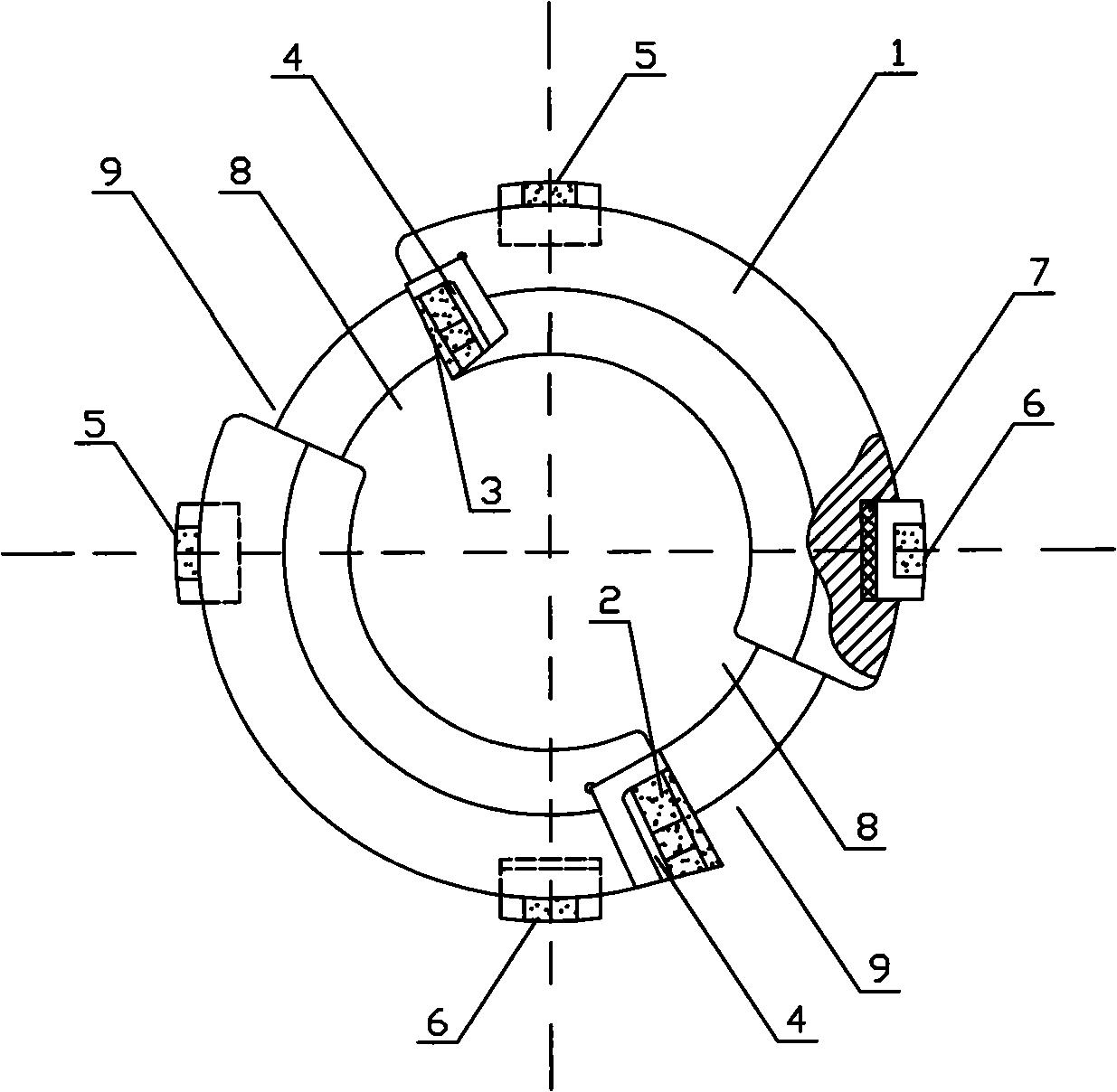
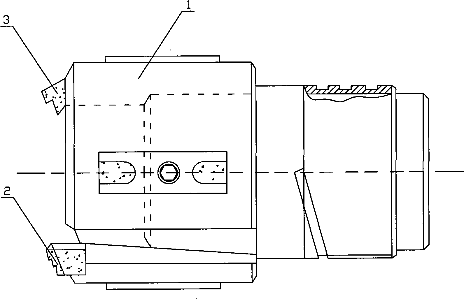
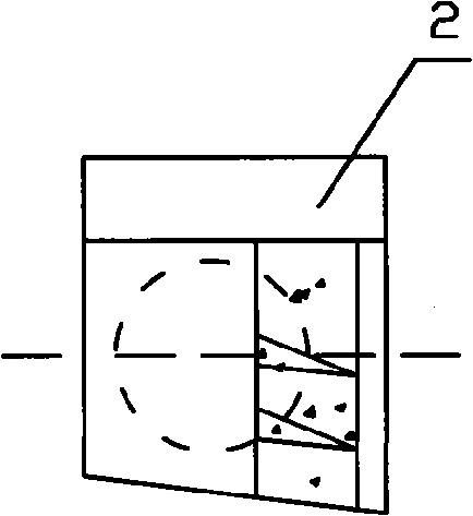
[0027] Such as figure 1 , figure 2 , image 3 , Figure 4 , Figure 5 and Figure 6 Shown: a taper-mounted eccentric machine ferrule drill, including a cutter body 1, an outer cutter 2, an inner cutter 3, a cutter pad 4, two guide keys 5, two elastic keys 6, and two oil-resistant rubber pads 7 , two oil inlet gaps 8, two chip removal gaps 9, and machine card handles and machine card taper screws;

[0028] The two chip removal gaps 9 are each equipped with a dovetail-shaped eccentric machine card. The outer knife 2 and the inner knife 3 are respectively installed on the respective machine cards through the machine card taper screws. The dovetail-shaped eccentric machine card at the front of the handle;

[0029] In other embodiments, it may also be: the outer knife 2 and the inner knife 3 are respectively brazed ...


PUM

PropertyMeasurementUnit
Slopeaaaaaaaaaa
Taperaaaaaaaaaa

Abstract

The invention provides a taper mounted type eccentric machine trepanning drill which comprises a cutter body, an outer cutter, an inner cutter, a shim, a guidance key, an elastic key, an oil resisting rubber jointing, an oil inletting clearance, a chip removal clearance, a machine card cutter holder and a machine card taper screw. The chip removal clearance is provided with an eccentric machine card of the cutter holder in a coattail shape; the outer cutter and the inner cutter are arranged in the eccentric machine card in a coattail shape at the front part of the machine card cutter holder respectively by machine card taper screw; the tail part of the machine card cutter holder is in a cylinder shape and the upper part of the cylinder is provided with inclined surface in shape of a umbrella with the gradient slope of 2 to 5; the machine card cutter holder tightly fastens the inclined surface in shape of a umbrella in the installing hole of the cutter body by screws; the outer cutter and the inner cutter are provided with at least one chip splitting table respectively; the outer edge of the cutter body is tightly provided with two guiding keys and two elastic keys by screws. The trepanning drill has the advantages of good cutting property, less vibration and good chip breaking effect, can meet the demand of product processing size and can reduce the roughness of the products on the basis of high-speed cutting.

Description

technical field [0001] The invention relates to a metal cutting tool, in particular to a taper-mounted eccentric machine ferrule drill for deep hole processing, which has radial cutting force and eliminates vibration. Background technique [0002] At present, the deep hole casing drill used in the prior art is to weld the cemented carbide blade on the handle with brass, and install the four knives on the annular cutter body through sharpening. The installation height sequence of the knife is different and the chip is separated, especially the cutting edge and the chip breaker are both 90 degrees. Cutting in the annular groove forms a non-radial force balanced cutting. Therefore, the guide key cannot be close to the machined surface. It cannot eliminate vibration and play a good guiding role. In addition, because the cutting edge and the chip breaker are parallel grooves, the chip breaking is poor, and it is even more difficult for materials that are difficult to break. [0...

Claims


Application Information

Patent Timeline
IPC IPC(8): B23B51/04B23B41/02
Inventor 田栽亮田清安
Owner 田栽亮
Why Eureka
Try Eureka