
NMR imaging equipment stability and method for measuring image-forming index

A nuclear magnetic resonance imaging and nuclear magnetic resonance technology, which is applied in the use of nuclear magnetic resonance imaging systems for measurement, magnetic resonance measurement, and magnetic variable measurement, etc. question

Inactive Publication Date: 2008-12-17
WEST CHINA HOSPITAL SICHUAN UNIV
View PDF0 Cites 29 Cited by
  • Summary
  • Abstract
  • Description
  • Claims
  • Application Information

AI Technical Summary

Problems solved by technology

The existing problems are mainly as follows: (1) The testing work is cumbersome: generally, before scanning the patient every day, the MRI equipment used in clinical practice must carry out the QA test of the equipment, that is, use the MRI scanner to conduct a QA test on the water model. Scan, and then process and measure the scanned image according to relevant methods, get QA indicators, analyze and record
This work is mainly done manually, and the process is cumbersome; (2) The test is highly subjective, and due to the lack of uniform standards for manual selection of the ROI area or central axis, the data is affected by the operator; (3) Recording and saving of parameters It is mainly done manually, which is not conducive to long-term preservation and statistical analysis of historical data
The state of equipment and its changes are obtained through the statistics of QA data over a long period of time. The lack of statistics cannot give full play to the importance of QA work, which is why QA work has not been fully implemented.
Although there are currently many related professional software to complete the QA process, these software are often provided by MRI equipment suppliers, and do not have general scanning data processing capabilities and simple external data interfaces.
On the other hand, some specialties have powerful functions, but there are too many manual interventions in the execution process, the operation is complicated, and even some programming design is required, which is not conducive to the work of radiographers.

Method used


Image

  • NMR imaging equipment stability and method for measuring image-forming index
  • NMR imaging equipment stability and method for measuring image-forming index
  • NMR imaging equipment stability and method for measuring image-forming index

Examples


Embodiment

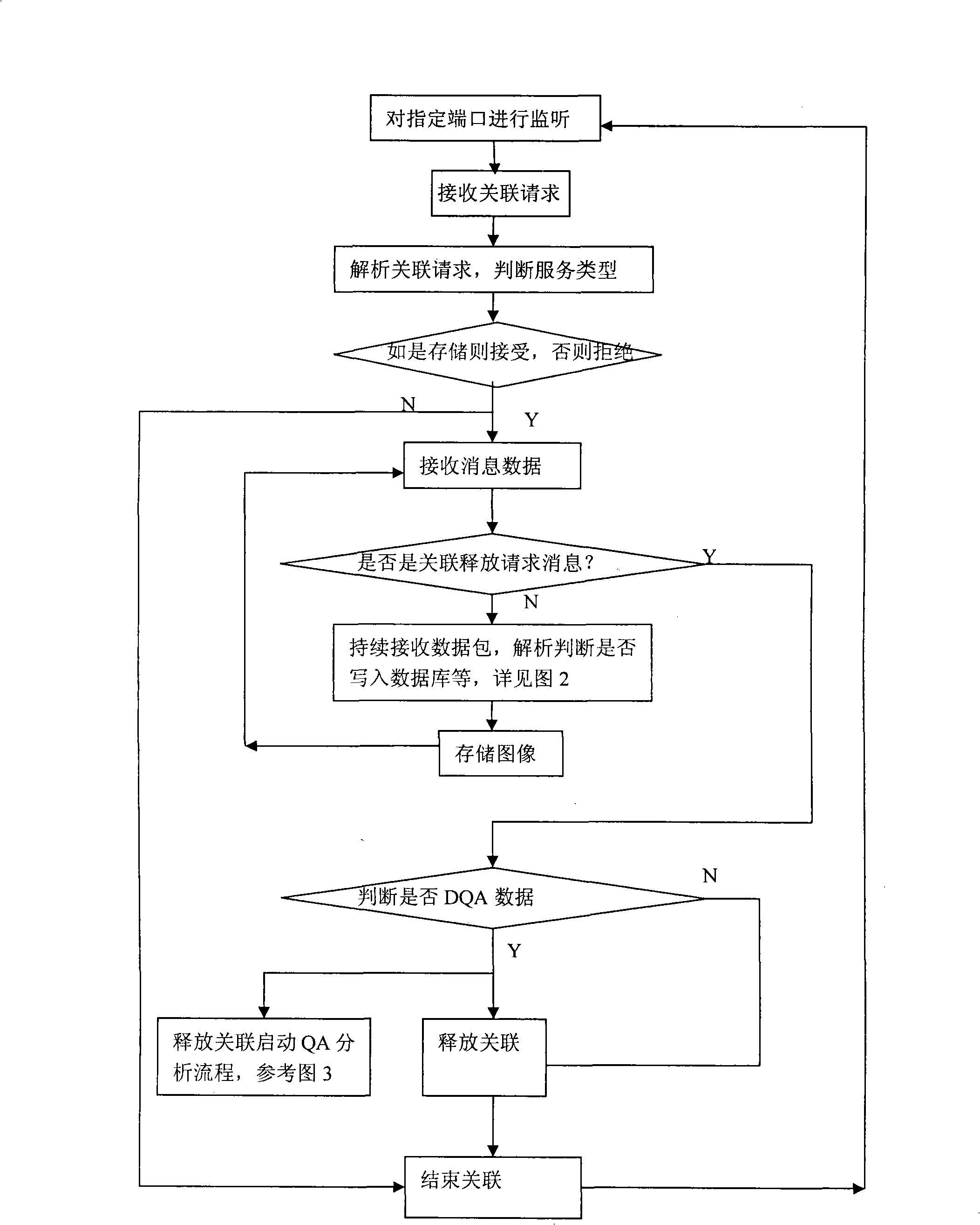
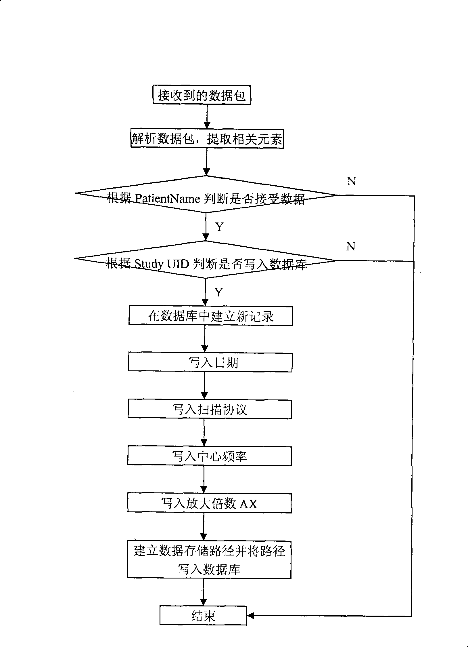
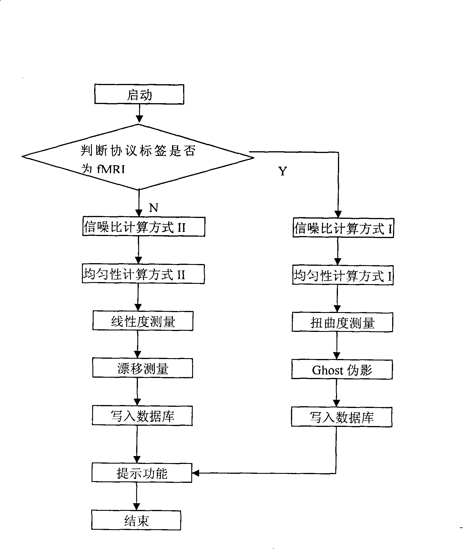
[0037] The client sends the image sequence of the scanned water model to the server using the DICOM protocol (the server is the QA data workstation, and the client is the equipment workstation), and the server determines whether to store and start the QA analysis process after judgment.

[0038]The server uses the DICOM protocol to complete the QA process control according to the following steps:

[0039] (1) When receiving an association request message from the client, decode the message and judge whether it is a storage class, if so, construct the response information A-AssociateAC PDU, and the client starts to transmit data; otherwise, reject it.

[0040] (2) The server receives the message data, decodes it and judges whether it is a release association request message; if it is and judges that the data is DQA data, releases the association and starts the QA analysis process. Otherwise, continue to receive data messages, and perform step 3 until receiving a release associa...


PUM


Abstract

The invention discloses a method for measuring the stability and imaging indexes of a nuclear magnetic resonance imaging device and is characterized in that: the images of a water phantom are obtained by adopting the nuclear magnetic resonance imaging device to scan the water phantom, the images are transmitted to a specific nuclear magnetic resonance imaging quality assurance and analysis work station by a DICOM protocol, and then the quality assurance and analysis work station is self started and enters a corresponding measurement process (referring to the figure 1 in the abstract of the process) according to DICOM control elements so as to process and calculate the images of the water phantom; the measuring content includes common nuclear magnetic resonance imaging quality assurance indexes, the shifting indexes which have important significance to Functional MRI, and other indexes; meanwhile, an automatic early warning mechanism is established for auto prompting when an abnormal condition occurs and gives the possible reason, and all measured results are sent into a database for long-term analysis of data and evaluation of running state of the device, so as to offer guidance to relevant technicians to master device state and carry out equipment testing.

Description

technical field [0001] The invention relates to a method for measuring the stability of nuclear magnetic resonance imaging equipment and imaging indexes, and belongs to the application field of nuclear magnetic resonance imaging equipment. Background technique [0002] Since the first nuclear magnetic resonance scanner came out in 1972, magnetic resonance imaging (Magnetic Resonance Image, MRI) has been developed rapidly as an important clinical examination method, and plays an important role in clinical diagnosis. At the same time, the imaging methods of nuclear magnetic resonance are also advancing with each passing day, and some new imaging technologies including functional magnetic resonance imaging (functional Magnetic Resonance Image, fMRI) have emerged. However, as a very complex system, MRI is affected by many factors and links, and there are many unstable factors in the equipment itself, which are finally reflected in imaging quality problems, leading to misdiagnosi...

Claims


Application Information

Patent Timeline
Patent Type & Authority Applications(China)
IPC IPC(8): A61B5/055G01R33/54
Inventor 龚启勇幸浩洋唐鹤菡王存玖黄晓琦吕粟
Owner WEST CHINA HOSPITAL SICHUAN UNIV
Learn More