Lift augmenter with united jet flow structure on wing flap

A technology of combined jet flow and high-lift device, which is applied in the field of devices for improving the aerodynamic characteristics of aircraft take-off and landing, and high-lift device, which can solve the problems of increasing the complexity of the wing structure and increasing the weight of the aircraft, so as to improve the quality of air flow and reduce the Wing area, effect of reducing wing weight

Inactive Publication Date: 2008-12-17
BEIHANG UNIV
View PDF0 Cites 45 Cited by
  • Summary
  • Abstract
  • Description
  • Claims
  • Application Information

AI Technical Summary

Problems solved by technology

[0002] The existing method of improving the lift coefficient of the aircraft and the lift of the wing is usually to make the wing into a multi-section airfoil, such as figure 1 In the multi-section win

Method used


Image

  • Lift augmenter with united jet flow structure on wing flap
  • Lift augmenter with united jet flow structure on wing flap
  • Lift augmenter with united jet flow structure on wing flap

Examples


Embodiment Construction

[0023] The present invention will be further described in detail with reference to the accompanying drawings and embodiments.

[0024] The invention relates to a lift-increasing device with a combined jet structure on the flap, which can increase the lift coefficient of the wing and improve the flight quality.

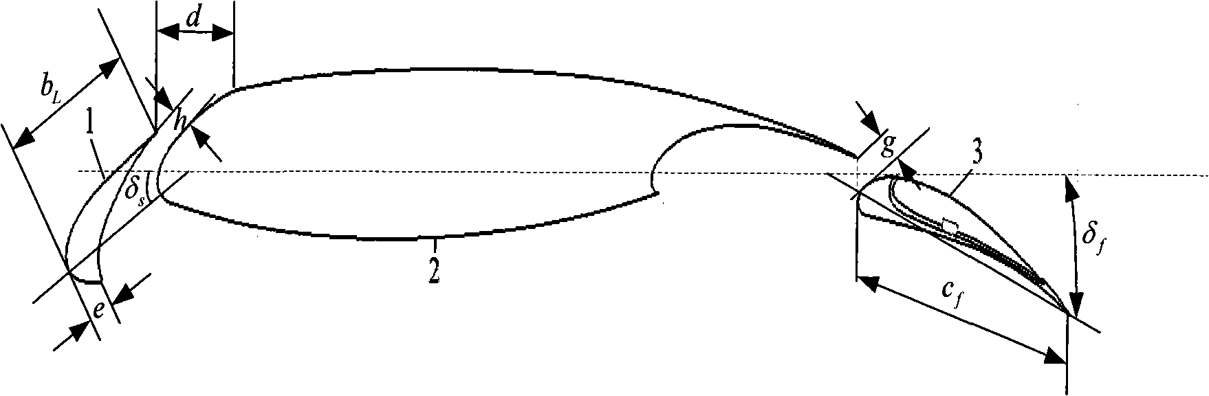
[0025] like image 3 As shown, the high-lift device includes: the slat 1 at the leading edge of the wing, the main body part 2, and the flap 3, the slat 1 at the leading edge of the wing h=3%c, and the overhang d= 11% c, slat 1 chord length b L =15%c, the chord length of the lower airfoil e=4%c, the deflection angle of slat 1 is at take-off δ s = 20°, δ at landing s =25°, the letter c is the wing chord length.

[0026] The flap 3 setting parameters are as follows image 3 As shown, the gap g=1.26%c, the flap 3 chord length c f = 30% c, deflection angle at takeoff δ f = 20°, δ at landing f = 40°.

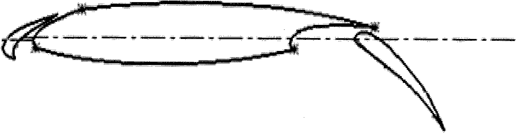
[0027] The flap 3 has a combined jet structure, such as Figur...


PUM


Abstract

The invention discloses a height-lift device provided with combined jet structure on a wing flap, comprising a wing leading edge slat, a main wing and the wing flap; wherein, the upper surface of the wing flap is provided with the combined jet structure which is provided with an air compressor used for controlling the flow and the speed of ejective airflow so as to adjust the influence of the airflow on the taking-off or landing performances of a plane. The high-lift device can obviously improve the flow quality above the wing flap of the plane, avoid the separation of the wing flap, improve the taking off, landing and stall performance of the plane, improve the maximum lift and furthermore, and achieve the taking off and landing of the plane at comparatively low speed.

Description

technical field [0001] The invention belongs to the technical field of aviation aerodynamics, and relates to a device capable of improving the aerodynamic characteristics of aircraft take-off and landing, in particular, it refers to a lift-increasing device with combined jets on flaps. Background technique [0002] The existing method of improving the lift coefficient of the aircraft and the lift of the wing is usually to make the wing into a multi-section airfoil, such as figure 1 In the multi-section wing airfoil structure shown, the wing is divided into three sections, but after the section design, the complexity of the wing structure increases, which will inevitably increase the weight of the aircraft. [0003] Another method is to add a combined jet structure on the main airfoil, such as figure 2 The schematic diagram of the high-lift device with combined jets on the wing is shown. It can be seen from the figure that the upper surface of the wing is provided with a co...

Claims


Application Information

Patent Timeline
IPC IPC(8): B64C3/10B64C3/28B64C21/00
Inventor 刘沛清张东金立宁田云李成功
Owner BEIHANG UNIV
Why Eureka
Try Eureka