Supercharge Your Innovation With Domain-Expert AI Agents!

Lift augmenter with united jet flow structure on wing flap

A technology of combined jet and lift device, applied in the field of aerodynamics, can solve the problems of increasing the complexity of the wing structure and increasing the weight of the aircraft, so as to improve the air flow quality, reduce the wing area, and reduce the weight of the wing. Effect

Inactive Publication Date: 2010-08-18
BEIHANG UNIV
View PDF0 Cites 0 Cited by
  • Summary
  • Abstract
  • Description
  • Claims
  • Application Information

AI Technical Summary

Problems solved by technology

[0002] The existing method of improving the lift coefficient of the aircraft and the lift of the wing is usually to make the wing into a multi-section airfoil, the multi-section airfoil structure shown in Figure 1, the wing is divided into three sections, but after the section design , the complexity of the wing structure increases and inevitably increases the weight of the aircraft

Method used


Image

  • Lift augmenter with united jet flow structure on wing flap
  • Lift augmenter with united jet flow structure on wing flap
  • Lift augmenter with united jet flow structure on wing flap

Examples


Embodiment Construction

[0023] The present invention will be further described in detail below with reference to the drawings and embodiments.

[0024] The invention relates to a lifting device with a combined jet structure on a flap, which can increase the lift coefficient of the wing and improve the flight quality.

[0025] As shown in Figure 3, the lifting device includes: the slat 1, the main body part of the wing 2, the flap 3, the slat 1 at the leading edge of the wing, the gap h=3%c, and the extension Quantity d=11%c, slat 1 chord length b L =15%c, the chord length of the lower wing surface e=4%c, the slat 1 deflection angle is δ during takeoff s =20°, δ at landing s = 25°, the letter c is the wing chord length.

[0026] The setting parameters of the flap 3 are shown in Figure 3, the gap g = 1.26% c, the chord length of the flap 3 c f =30%c, the deflection angle is δ at takeoff f =20°, δ at landing f = 40°.

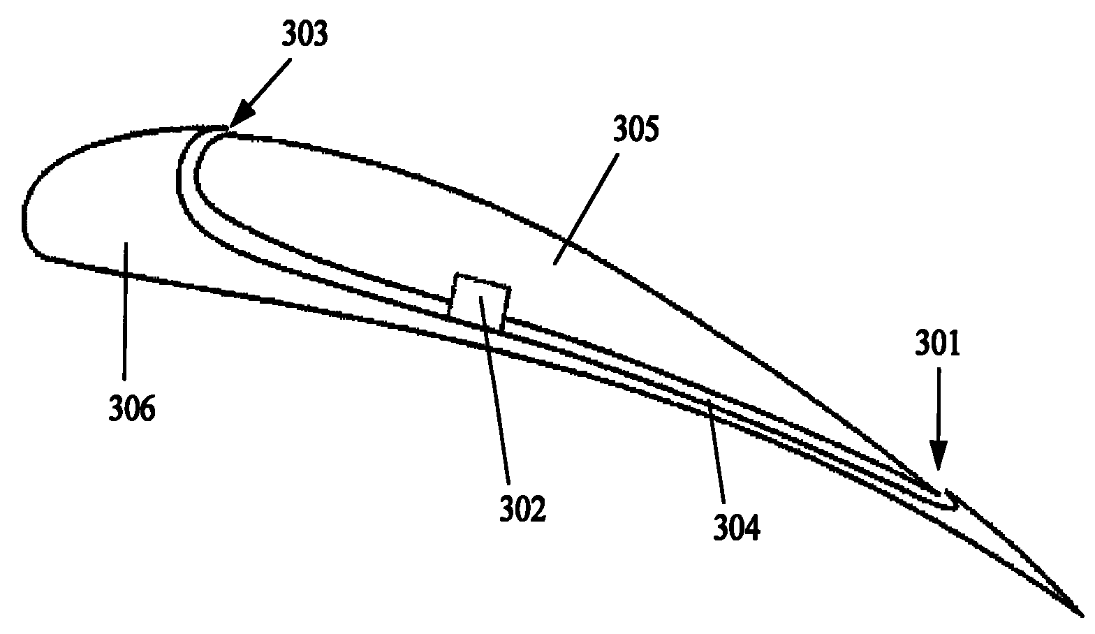
[0027] The flap 3 has a combined jet structure, as shown in FIG. 4, the combined jet structur...


PUM


Abstract

The invention discloses a height-lift device provided with combined jet structure on a wing flap, comprising a wing leading edge slat, a main wing and the wing flap; wherein, the upper surface of the wing flap is provided with the combined jet structure which is provided with an air compressor used for controlling the flow and the speed of ejective airflow so as to adjust the influence of the airflow on the taking-off or landing performances of a plane. The high-lift device can obviously improve the flow quality above the wing flap of the plane, avoid the separation of the wing flap, improve the taking off, landing and stall performance of the plane, improve the maximum lift and furthermore, and achieve the taking off and landing of the plane at comparatively low speed.

Description

Technical field [0001] The invention belongs to the technical field of aviation aerodynamics, and relates to a device capable of improving the aerodynamic characteristics of an aircraft during take-off and landing. Specifically, it refers to a lift-increasing device with a combined jet on a flap. Background technique [0002] The existing method of improving the lift coefficient of the aircraft and the lift of the wing is usually to make the wing into a multi-segment airfoil, such as the multi-segment wing airfoil structure shown in Figure 1. The wing is divided into three segments, but after the segmented design , The complexity of the wing structure increases, and it will inevitably increase the weight of the aircraft. [0003] Another method is to add a combined jet structure on the main wing surface. The schematic diagram of the lifting device with a combined jet on the wing is shown in Figure 2. It can be seen from the figure that the upper wing surface is 15% A joint jet str...

Claims


Application Information

Patent Timeline
Patent Type & Authority Patents(China)
IPC IPC(8): B64C3/10B64C3/28B64C21/00
Inventor 刘沛清张东金立宁田云李成功
Owner BEIHANG UNIV
Features
  • R&D
  • Intellectual Property
  • Life Sciences
  • Materials
  • Tech Scout
  • Unparalleled Data Quality
  • Higher Quality Content
  • 60% Fewer Hallucinations
Learn More