Mudflat wind electric field fan foundation structure

A technology for fan foundations and wind farms, which is applied in infrastructure engineering, underwater structures, water conservancy projects, etc., can solve the problems of long construction period and large amount of soil, and achieves low hoisting cost, reduced construction difficulty, and small hoisting height. Effect

Inactive Publication Date: 2008-12-17
SHANGHAI INVESTIGATION DESIGN & RES INST
View PDF0 Cites 7 Cited by
  • Summary
  • Abstract
  • Description
  • Claims
  • Application Information

AI Technical Summary

Problems solved by technology

The disadvantages are: firstly, the project requires a large amount of soil, and the source of the earthwork needs to be resolved; secondly, since the wind turbine hoisting platform must reach a certain bearing capacity, the filling work of the platform should be carried out in advance, and sufficient consolidation time should be arranged, so the construction The construction period is longer; third, the foundation platform and slope should be maintained during the use process (such as masonry face protection, throwing special-shaped blocks, etc.) to protect the wind turbine foundation
[0006] From the above analysis, it can be seen that due to the limitations of previous design schemes, there are some problems in construction, fan hoisting and project cost, etc.

Method used


Image

  • Mudflat wind electric field fan foundation structure
  • Mudflat wind electric field fan foundation structure

Examples


Embodiment Construction

[0014] The present invention will be further described below in conjunction with the accompanying drawings and embodiments.

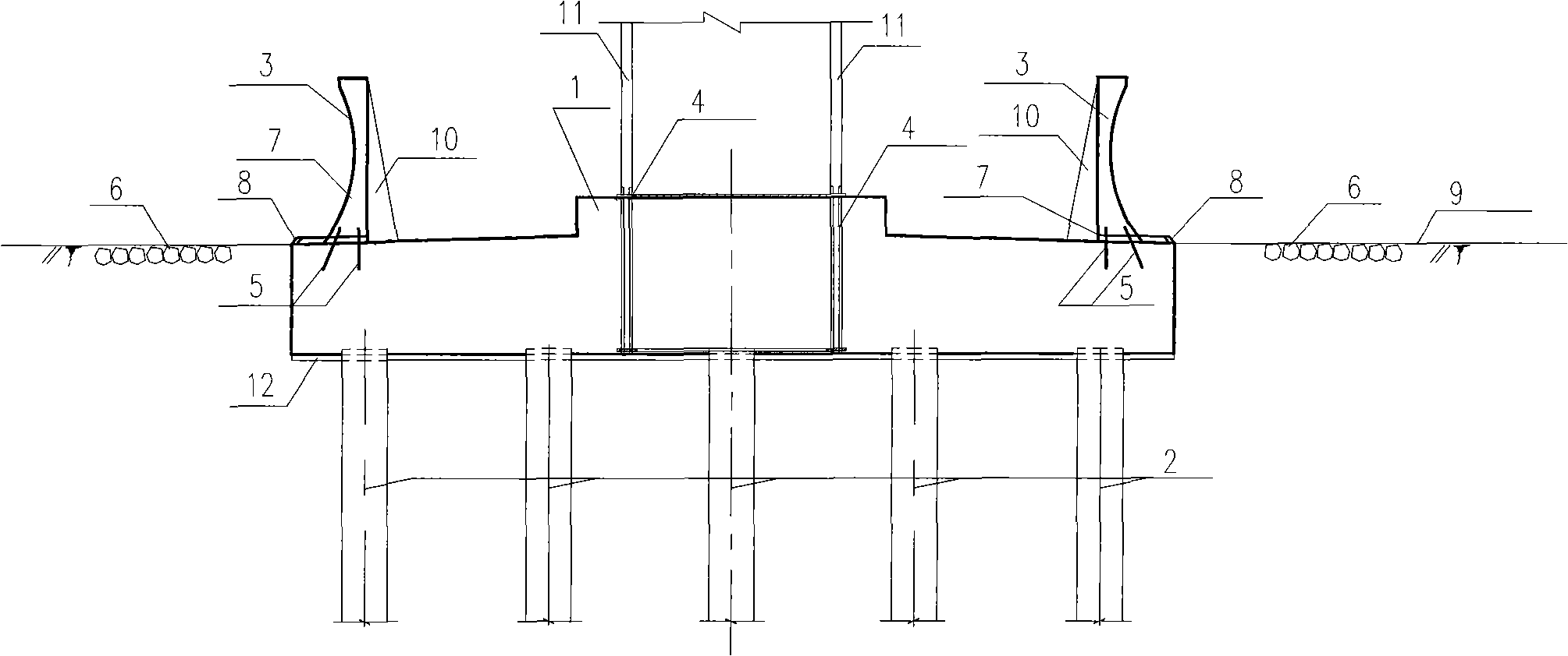
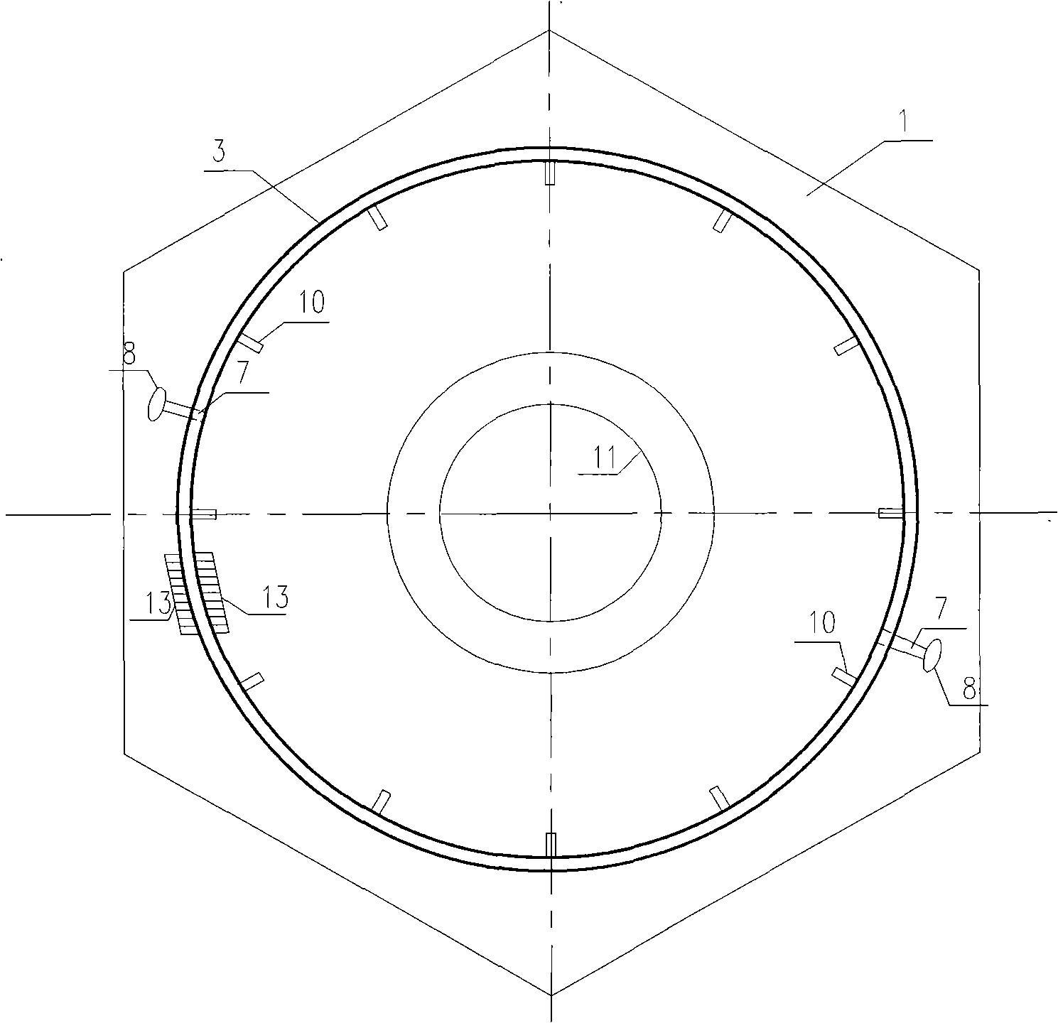
[0015] A tidal flat wind farm fan base structure, such as figure 1 , 2 As shown in the figure:

[0016] 1. Reinforced concrete foundation, 2. Pile foundation, 3. Wave wall, 4. Embedded parts of fan tower, 5. Reinforcement reserved for wave wall, 6. Anti-scour facilities, 7. Drainage groove, 8. One-way Valve, 9. Tidal flat surface, 10. Rib, 11. Fan tower tube, 12. Foundation cushion, 13. Ladder.

[0017] Taking the tidal flat wind farm site as an example with weak foundation soil, the reinforced concrete foundation 1 generally requires the establishment of a pile foundation 2, and the lower part of the reinforced concrete foundation 1 should be paved with the foundation cushion 12 first, and the wind tower should be erected before the reinforced concrete foundation 1 is poured. Frame pre-embedded parts 4, fan tower pre-embedded parts 4 are connected w...


PUM


Abstract

The invention relates to a fan foundation structure in the beach wind power field, mainly comprising a fan foundation upper bearing platform, a barrel-shaped foundation structure type formed by the surrounding wave walls and a drainage facility which is arranged on the foundation surface and drains the water from interior to the exterior. The top surface elevation of the fan foundation can be appropriately lifted up according to the elevation of beach surface; the wave walls which are arranged around the foundation are used for retaining the tidewater, so as to ensure that the fan tower frame steel structure is not soaked and corroded by the seawater. During the construction of the fan foundation, the foundation construction difficulty is reduced owing to the small elevation difference of the casting surface and the beach surface; after the existing beach surface is locally levelled and structurally disposed, a fan hoisting platform can be directly formed, thus reducing the engineering quantity of cubic metre of earth and stone of the fan hoisting platform, saving the engineering investment and shortening the construction period; on the fan hoisting aspect, as the hoisting platform is basically flush with the fan foundation surface, the fan foundation structure has the advantages of smaller hoisting height, convenient hoisting, and low hoisting expense, etc. compared with the existing beach fan foundation types.

Description

technical field [0001] The invention relates to a basic structure of a wind turbine in a tidal flat wind farm. Background technique [0002] According to the construction site, wind farms can be divided into onshore and offshore. In my country, the construction of offshore wind farms has not yet been formally implemented, and the available coastline for onshore wind farm construction is limited. Therefore, investors gradually consider building wind farms beyond the seawall to the depth of the outer sea shoal, forming tidal flat wind farms. . The construction and operation of tidal flat wind farms are affected by the ebb and flow of seawater. Generally, the wind turbine foundation construction is protected by temporary cofferdams and can be constructed in dry land. However, due to the damage of cofferdams or low cofferdam standards during operation , the tide directly surrounds the fan foundation. In order to avoid the immersion and erosion of seawater or waves on the steel...

Claims


Application Information

Patent Timeline
Patent Type & Authority Applications(China)
IPC IPC(8): E02B17/00
Inventor 沈达江波李健英
Owner SHANGHAI INVESTIGATION DESIGN & RES INST
Why Eureka
Try Eureka