
Microscope for observing a sample in the bright field illumination by transmitted light or in fluorescence-contrast epi-illumination

A microscope and transmitted light technology, applied in the field of microscopy, can solve problems such as loss, and achieve the effect of eliminating error sources

Active Publication Date: 2008-12-17
CARL ZEISS MIKROLMAGING
View PDF0 Cites 10 Cited by
  • Summary
  • Abstract
  • Description
  • Claims
  • Application Information

AI Technical Summary

Problems solved by technology

The disadvantage is that due to the mechanical separation of the fixedly installed filter group and the fixedly installed light source, the possibility of selecting different fluorescence wavelengths on the user side is lost

Method used


Image

  • Microscope for observing a sample in the bright field illumination by transmitted light or in fluorescence-contrast epi-illumination
  • Microscope for observing a sample in the bright field illumination by transmitted light or in fluorescence-contrast epi-illumination
  • Microscope for observing a sample in the bright field illumination by transmitted light or in fluorescence-contrast epi-illumination

Examples


Embodiment Construction

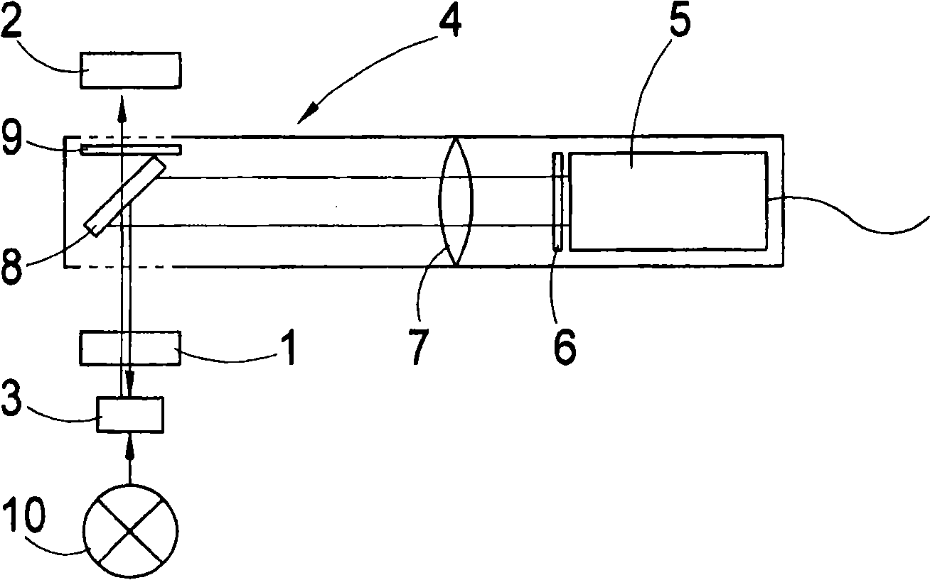
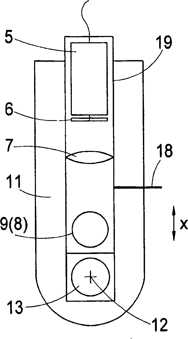
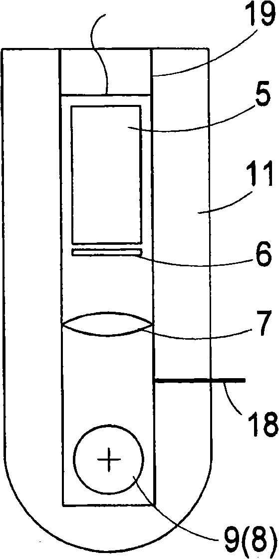
[0052]figure 1 Only the important components of the microscope beam path relevant to the description of the invention, namely the microscope objective 1 and the microscope barrel 2 , are shown symbolically. The object 3 to be observed is likewise shown. With the help of figure 1 The fluorescent module 4 according to the invention, which is shown in side view, makes it possible to observe an object 3 in fluorescent reflected light contrast. For this purpose the phosphor assembly 4 has:

[0053] - LED 5, which for example emits light with a wavelength of approximately 470 nm,

[0054] - excitation filter 6, which in this case is only transparent for light with a wavelength of 450 nm to 490 nm,

[0055] - illumination optics 7 for illuminating the object 3 with light from the LED 5,

[0056] - a beam splitter 8, the splitter layer of which reflects excitation beams of wavelength 500 nm, and

[0057] - Emission filter 9, which only transmits the emission beam >510 nm.

[00...


PUM


Abstract

The invention relates to a microscope for observing a sample in bright-field transmitted light contrast procedure or the incident-light fluorescence contrast procedure. The microscope is used for observing an object selectably using the bright-field transmitted light contrast procedure or the incident-light fluorescence contrast procedure. During the bright-field transmitted light contrast procedure, an illumination beam path is directed from a bright-field light source to the object and an imaging beam path is directed from the object through the microscope objective into the microscope tube, wherein a fluorescence unit is composed of a fluorescence excitation light source, an illumination optical system, a filter set having at least one excitation filter and at least one emission filter, as well as a beamsplitter. The fluorescence unit is mounted movably, so that in a first end position of movement, the beamsplitter and the emission filter are out of the imaging beam path of the microscope and in a second end position of movement, the beamsplitter and the emission filter are in the imaging beam path between the microscope objective and the microscope tube.

Description

technical field [0001] The present invention relates to a microscope for selectively observing objects by bright field transmitted light contrast method or fluorescent reflected light contrast method. Background technique [0002] In microscopes, especially in optical microscopes for observing objects by brightfield transmitted light contrast, the microscope light path leads from the brightfield light source through the object and through the microscope objective into the microscope barrel. [0003] Furthermore, microscopes constructed for observation of objects by means of fluorescence-reflected-light contrast additionally have a fluorescence device consisting essentially of the following components: [0004] - sources of multispectral emission, such as the arc lamp HBO with a linear spectrum, or [0005] - arc lamp XBO with continuum, or [0006] - light sources emitting in a narrow band, such as LEDs (Light Emitting Diodes), and [0007] - optics for imaging light sour...

Claims


Application Information

Patent Timeline
Patent Type & Authority Applications(China)
IPC IPC(8): G02B21/06G02B21/00
CPCG02B21/088G02B21/12G02B21/14G02B21/16
Inventor A·诺尔特T·博彻I·法尔布什
Owner CARL ZEISS MIKROLMAGING
Learn More