
Magnetic bearing device

A technology of magnetic bearings and rolling bearings, applied in bearings, shafts and bearings, rolling contact bearings, etc., can solve the problems of unstable magnetic bearing control system and complicated controller, and achieve simplified structure, stable control objects, and reduced heat generation Effect

Inactive Publication Date: 2008-12-17
NTN CORP
View PDF2 Cites 9 Cited by
  • Summary
  • Abstract
  • Description
  • Claims
  • Application Information

AI Technical Summary

Problems solved by technology

[0017] However, in a magnetic bearing device using such a rolling bearing and a magnetic bearing in combination, when an excessive axial load acts, the negative rigidity of the electromagnet (acting in the direction of displacement, the greater the displacement, the greater the force) ) increases, the negative rigidity of the electromagnet is greater than the rigidity of the composite spring formed by the rolling bearing and the supporting system of the rolling bearing, at this time, the control system of the magnetic bearing is unstable
In order to avoid this state, there is a problem that it is necessary to add a phase compensation circuit to the controller in advance, which constitutes one of the reasons for the complexity of the controller.

Method used


Image

  • Magnetic bearing device
  • Magnetic bearing device
  • Magnetic bearing device

Examples


Embodiment Construction

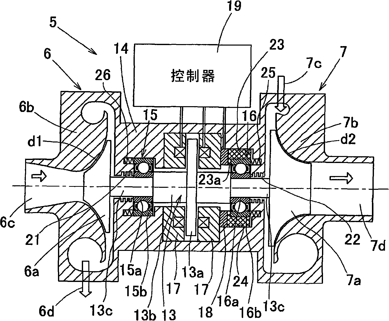
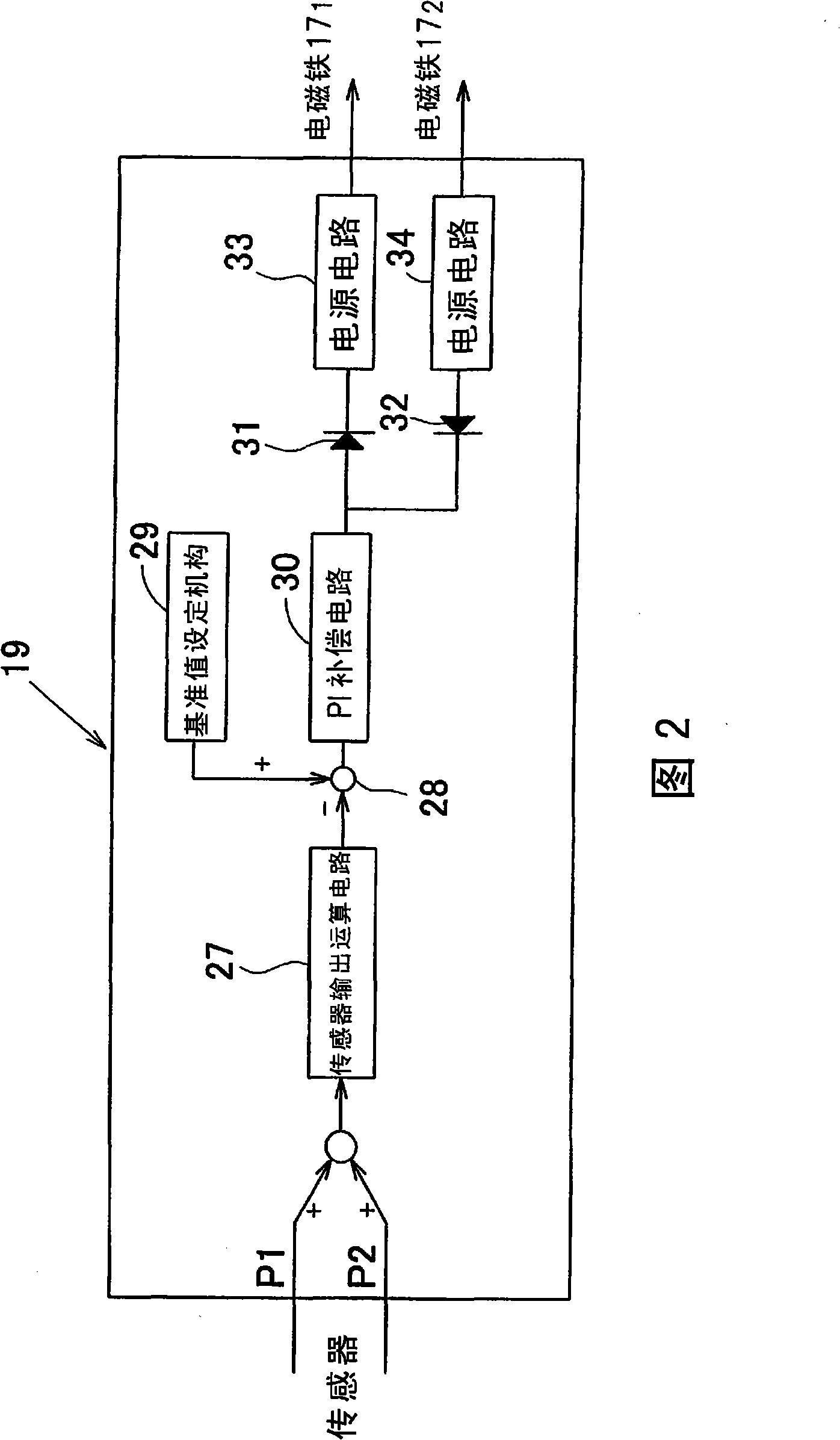
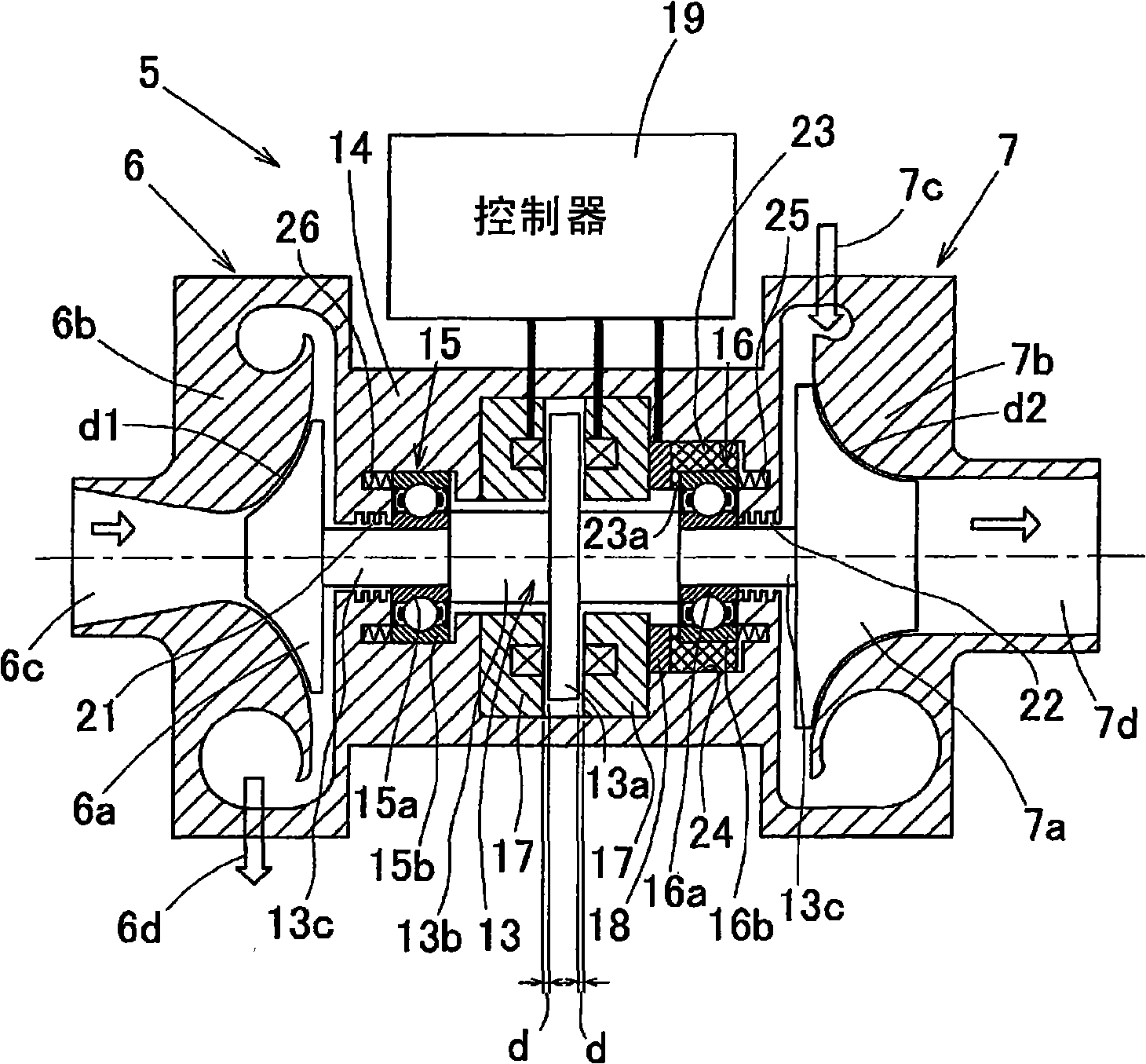
[0048] combine figure 1 A first embodiment of the present invention will be described with reference to FIG. 2 . figure 1 A sectional view showing a turbine assembly 5 incorporating the magnetic bearing device of the present invention. The turbine assembly 5 constitutes a compression-expansion turbine system, which includes a compressor 6 and an expansion turbine 7 , the compressor blades 6 a of the compressor 6 and the turbine blades 7 a of the expansion turbine 7 are mounted on both ends of the main shaft 13 . In addition, the compressor blade 6a is driven by power generated by the turbine blade 7a, and no separate drive source is provided.

[0049] The compressor 6 includes a casing 6b facing the compressor blade 6a through a small gap d1, and the air sucked in the axial direction from the suction port 6c in the center is compressed by the compressor blade 6a, and the air sucked in the axial direction from the suction port 6c in the center is compressed, not shown), disch...


PUM


Abstract

A magnetic bearing device is provided. The magnetic bearing device is stably controllable with a simplified-structure controller, and a roller bearing and a magnetic bearing are used in combination for the magnetic bearing device. The roller bearing and the magnetic bearing are used in combination in the magnetic bearing device, wherein the roller bearing supports a radial load while the magnetic bearing supports either the axial load or precompression or both. An electromagnet (17) is provided at a spindle housing (14) opposite in non-contact to a flange-like thrust plate (13a) which is fixed perpendicularly and coaxially at a main spindle (13) and which is made of ferromagnetic materials. A sensor (18) is provided to detect an axial direction force to act on the roller bearing and a controller (19) is further provided to control electromagnet (17) in response to an output of the sensor (18). The bearing device has the relationship that a resultant spring-stiffness value formed by the roller bearing and its supporting system is larger than a minus stiffness value of the electromagnet.

Description

technical field [0001] The present invention relates to a magnetic bearing device, which uses a rolling bearing and a magnetic bearing in combination, and through the magnetic bearing, any one or both of axial load and bearing preload is supported. The present invention relates to, for example, a turbine in an air circulation refrigeration cooling system Magnetic bearing devices used in components, etc. Background technique [0002] In the air cycle refrigeration system, since air is used as the refrigerant, the energy efficiency is insufficient compared with the case where fluorocarbon refrigerant, ammonia gas, etc. are used, but it is good in terms of environmental protection. In addition, like freezers, etc., in facilities that can directly blow in cooling air, there is a possibility of reducing the total cost due to the omission of fans and defrosters in the storage. In such applications, air circulation refrigeration is proposed. Cooling system (for example, Patent Doc...

Claims


Application Information

Patent Timeline
Patent Type & Authority Applications(China)
IPC IPC(8): F16C32/00F16C25/06F16C32/04F01D25/16
Inventor 尾崎孝美山田裕之铃木健一
Owner NTN CORP
Learn More