
Apparatus for preventing carbon corrosion at cathod in fuel cell

A fuel cell cathode and fuel cell technology, applied in the direction of fuel cells, fuel cell additives, solid electrolyte fuel cells, etc., can solve problems such as inconvenience, adverse effects on fuel cell durability performance, and gas burner safety issues

Inactive Publication Date: 2008-12-24
HYUNDAI MOTOR CO LTD +1
View PDF10 Cites 8 Cited by
  • Summary
  • Abstract
  • Description
  • Claims
  • Application Information

AI Technical Summary

Problems solved by technology

[0025] However, the use of gas burners has safety concerns and requires additional equipment
This additional unit requires more power and space in the design
[0026] Also, using nitrogen cylinders has some problems: it requires the extra installation of nitrogen cylinders in the transport, and the cylinders must be refilled when the nitrogen is exhausted
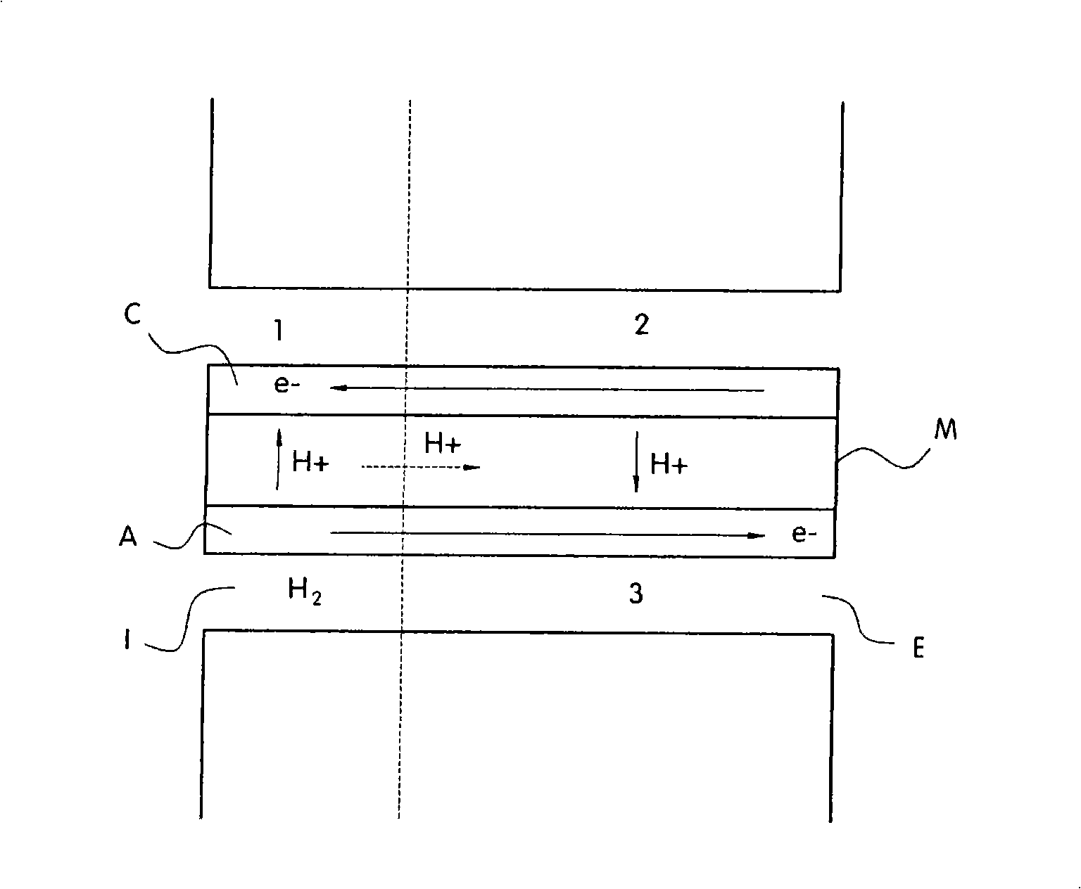
[0027] In addition, purging air during fuel cell shutdown inevitably creates a hydrogen / oxygen interface on the anode, which shortens the time the anode is filled with air, thereby damaging fuel cell performance
[0028] Also, in the device and method using this fuel cell startup / shutdown process, startup and shutdown are very time-consuming, which causes inconvenience
[0029] Therefore, prior art devices and methods have a detrimental effect on the durability performance of the fuel cell
Also, if the hydrogen off-gas and air off-gas are exposed to the air, there is a possibility of damage to the fuel cell due to pollutants in the ambient air

Method used


Image

  • Apparatus for preventing carbon corrosion at cathod in fuel cell
  • Apparatus for preventing carbon corrosion at cathod in fuel cell
  • Apparatus for preventing carbon corrosion at cathod in fuel cell

Examples


Embodiment Construction

[0069] Reference is now made in detail to specific embodiments of the present invention, examples of which are illustrated in the accompanying drawings, wherein like elements are designated by like reference numerals throughout. Embodiments are described below, by referring to the appended Figure 3-7 to explain the present invention.

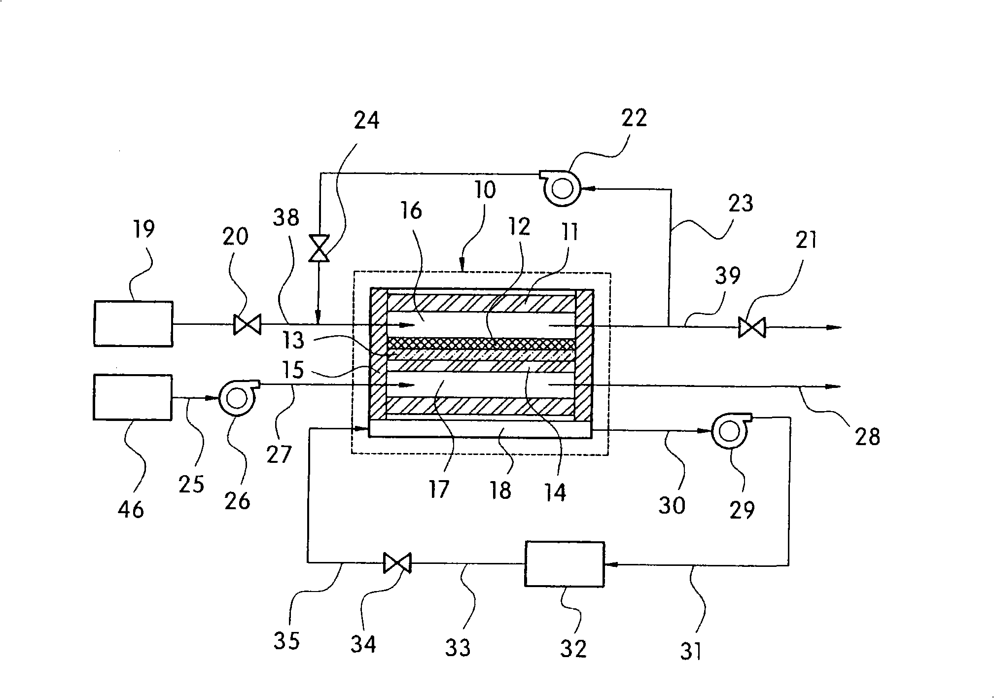
[0070] As mentioned above, the existing technology has the following problems: 1) complex structure (resistance, hydrogen burner in hydrogen recirculation line, nitrogen tank, etc.); 2) complex startup / shutdown process takes too much time; 3) Reduced performance stability due to air flow into the anode during startup / shutdown using additional devices; and 4) reduced stability due to contamination of the fuel cell due to exposure of hydrogen off-gas and air off-gas to air.

[0071] For example, moisture in fuel cells can evaporate under dry atmospheric conditions, and humidification water in MEAs is evaporated, resulting in reduced performance....


PUM


Abstract

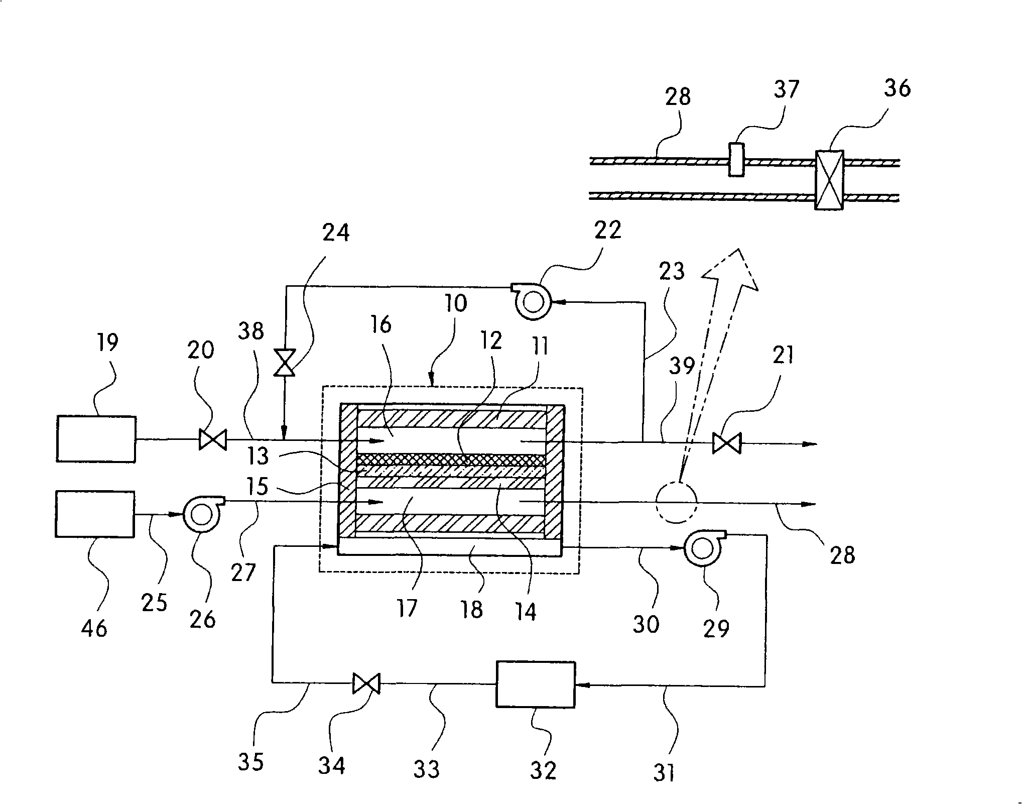
The present invention provides an apparatus for effectively preventing carbon corrosion from occurring at the cathode of a fuel cell. The present apparatuses include an air blower supplying air from an air supply source to a fuel cell; a fuel cell receiving air from the air blower to generate electricity by a chemical reaction; an air discharge pipe through which residual air remaining after oxygen of the air is consumed for chemical reaction in the fuel cell is discharged; a pressure sensor provided in the air discharge pipe for detecting air pressure in the fuel cell; an air discharge solenoid valve provided in the air discharge pipe for controlling air flow of the air discharge pipe; and a controller controlling operation of the air blower and the air discharge solenoid valve by receiving a signal detected by the pressure sensor wherein the controller detects the air pressure through the pressure sensor to allow the air blower to supply air to the fuel cell until the air pressure reaches a predetermined pressure and then closes the air discharge solenoid valve until the oxygen in the fuel cell is completely exhausted, thereby preventing the formation of hydrogen / oxygen interface at the anode of the fuel cell.

Description

[0001] This application claims priority under 35 U.S.C. §119(a) to Korean Patent Application No. 10-2007-0060912 filed June 21, 2007, which is hereby incorporated by reference in its entirety. field of invention [0002] The present invention relates to a device for preventing carbon corrosion on the cathode of a fuel cell by preventing the formation of a hydrogen / oxygen interface at the anode of the fuel cell during start-up and shutdown of the fuel cell. Background technique [0003] A fuel cell serving as a main power source of a fuel cell vehicle generates power through a reaction between oxygen provided by air and hydrogen stored in a fuel tank of the vehicle. [0004] figure 1 is a schematic diagram of a fuel cell system in a fuel cell vehicle. The fuel cell 10 includes a separator 11 , an anode 12 , an electrolyte membrane 13 , a cathode 14 , a hydrogen / oxygen / coolant distribution structure 15 , an anode flow field 16 , a cathode flow field 17 and a coolant flow fiel...

Claims


Application Information

Patent Timeline
Patent Type & Authority Applications(China)
IPC IPC(8): H01M8/04H01M8/10
CPCH01M8/04089H01M8/0441H01M8/04753H01M8/04761Y02E60/50Y10T137/7837H01M8/04H01M8/06
Inventor 吴承灿李钟贤尹钟震高载准金永敏孙翼齐
Owner HYUNDAI MOTOR CO LTD
Learn More