
Thermal shrinkage type composite casing tube for cable midst joint and manufacturing method thereof

A technology of cable intermediate joint and composite sleeve, which is applied to cable joints, circuits, electrical components, etc., can solve the problems of complicated cable installation process, partial discharge, low power frequency withstand voltage, etc., and achieves simple process and high safety. , the effect of high power frequency withstand voltage

Active Publication Date: 2010-07-07
CHANGYUAN GRP
View PDF6 Cites 0 Cited by
  • Summary
  • Abstract
  • Description
  • Claims
  • Application Information

AI Technical Summary

Problems solved by technology

[0005] The technical problem to be solved by the present invention is to solve the complicated cable installation process caused by the use of stress control tubes and two-layer composite tubes for insulation and shielding when installing cable intermediate joints in the prior art, and partial discharges often exist at the joints after cable installation. To solve the problems of low power frequency withstand voltage, and provide a heat-shrinkable cable intermediate joint composite sleeve with a three-layer structure, simple cable installation process, and high power frequency withstand voltage

Method used


Image

  • Thermal shrinkage type composite casing tube for cable midst joint and manufacturing method thereof
  • Thermal shrinkage type composite casing tube for cable midst joint and manufacturing method thereof
  • Thermal shrinkage type composite casing tube for cable midst joint and manufacturing method thereof

Examples


Embodiment 1

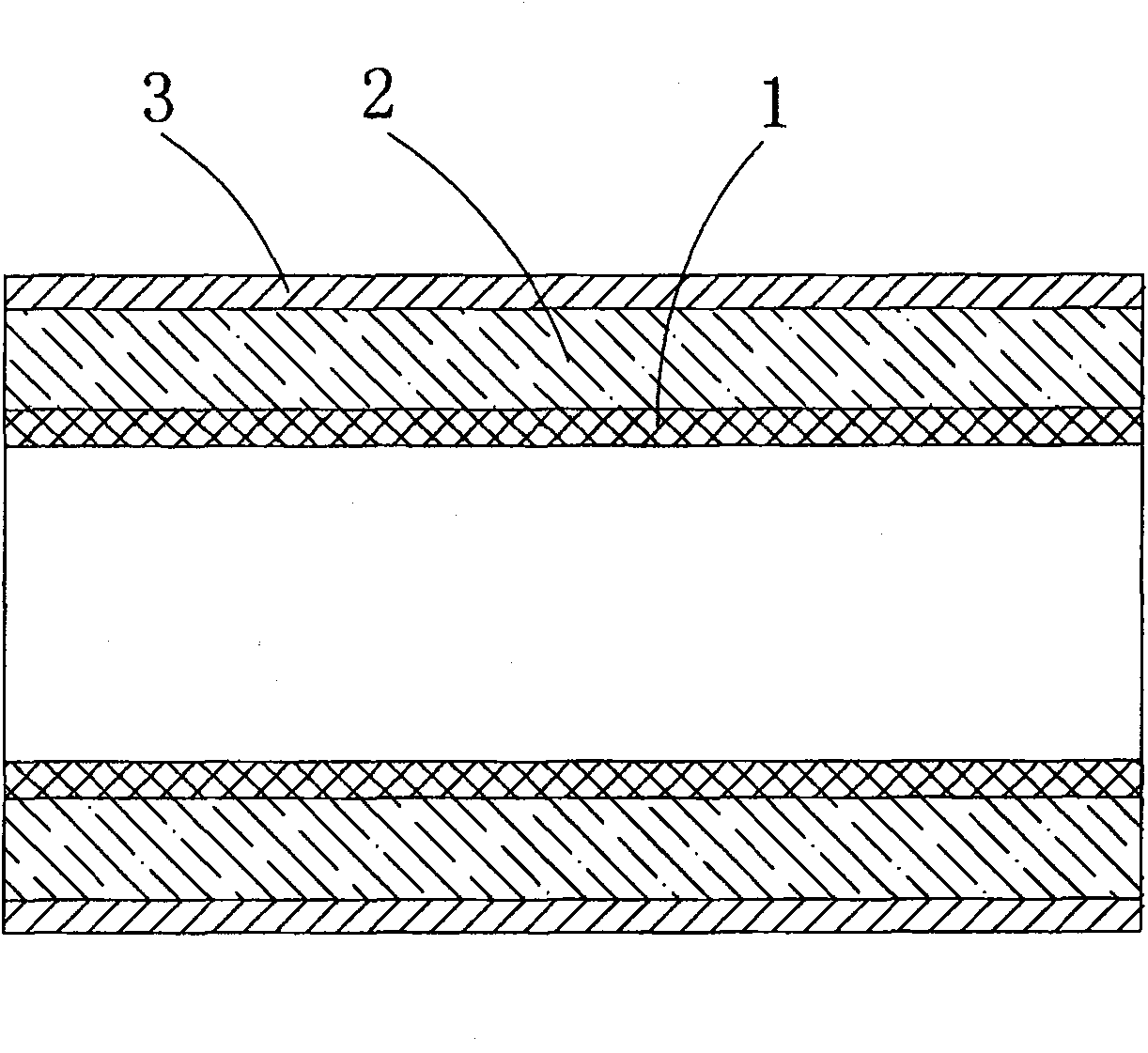
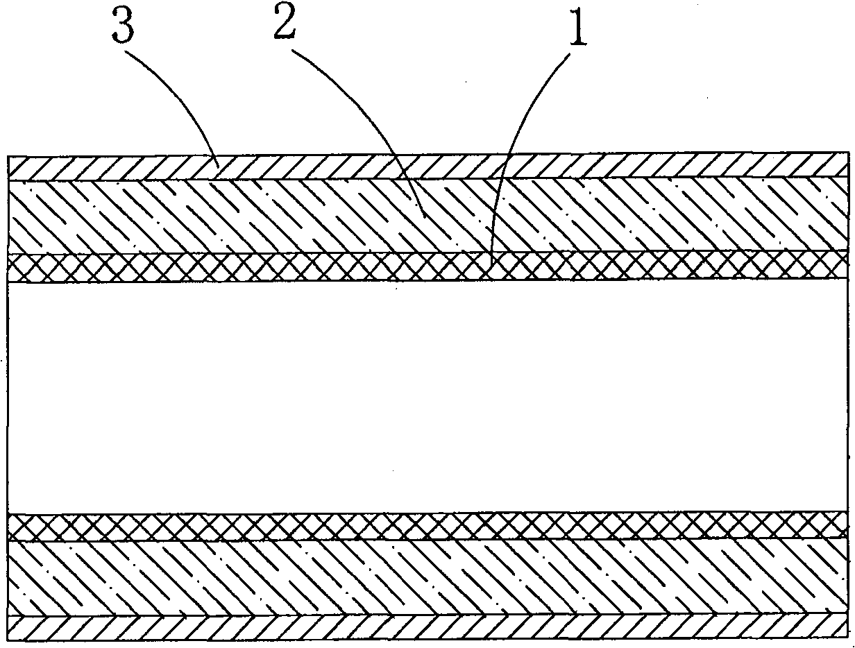
[0041] 8.7 / 15kV XLPE insulated power cable, core size 3×185mm 2 Take the cable intermediate joint composite sleeve as an example. Such as figure 2 As shown, the heat-shrinkable cable intermediate joint composite sleeve is in the shape of a round tube, and it has a three-layer composite structure. Conductive shielding layer 3 constitutes. The three layers are composed of three functional plastics of semi-conductive shielding, insulation and stress control respectively plasticized and co-extruded by a plastic extruder.

[0042] Wherein: the component of the material of stress control layer is (weight ratio): the EVA (VA=18%, MI=1.5) of 70 parts, the EPDM (4045) of 30 parts, 16 parts are made of conductive carbon black and high wear-resistant carbon Black is a combination of carbon black made of 1:3, 50 parts of BaTiO 3 (≥800 mesh), 1 part of antioxidant (1010), 1 part of silane coupling agent.

[0043] The material components of the insulating layer are (weight ratio): 33 ...

Embodiment 2

[0051] In this embodiment, the material composition of the stress control layer is (weight ratio): 50 parts of EVA (VA=18%, MI=1.5), 30 parts of EPDM, 20 parts of LDPE (MI=2.0), 16 parts of combined carbon Black (superfine grade), 52 parts BaTiO 3 (≥800 mesh), 1 part antioxidant (1010), 2 parts silane coupling agent.

[0052] The material composition of the insulating layer is (weight ratio): 25 parts of LDPE (MI=2.0), 10 parts of LLDPE (MI=1.5), 65 parts of EVA (VA=18%, MI=1.5), 15 parts of Al(OH) 3 After activation treatment, 1 part of antioxidant (1010), appropriate amount of toner.

[0053] The material composition of the semi-conductive shielding layer is (by weight) 30 parts of LDPE (MI=2.0), 60 parts of EVA (VA=18%, MI=1.5), 10 parts of POE, 30 parts of conductive carbon black (ultra-fine grade) , 1 part zinc stearate, 1 part antioxidant (1010);

[0054] The stress control layer, insulating layer and semi-conductive shielding layer are respectively plasticized with a...


PUM

PropertyMeasurementUnit
thicknessaaaaaaaaaa
electrical resistivityaaaaaaaaaa
thicknessaaaaaaaaaa

Abstract

The invention relates to a composite bushing of a heat shrinkable cable intermediate joint, which comprises a three-layer composite structure composed of a stress control layer, an insulating layer and a semiconduction shielding layer from the inner part to the outer part, and solves the problems of the complicated assembling procedures, the partial discharge and the low power frequency withstandvoltage caused by the laying assembly of a stress control tube, an insulating tube and a semiconduction shielding tube in the cable intermediate joint. The invention also provides a method for manufacturing the composite bushing, which comprises the following steps: the stress control, the insulating and the semiconduction shielding functional plastic materials are respectively plasticized and then co-extruded and formed through a plastic extruding machine, and the composite bushing of the heat shrinkable cable joint is obtained by radiation crosslinking, expanding and shaping after the extrusion. The composite bushing of the heat shrinkable cable joint of the invention has the advantages of high power frequency withstand voltage, no partial discharge and simple applying and assembling procedures, and the materials satisfy the environmental protection requirements.

Description

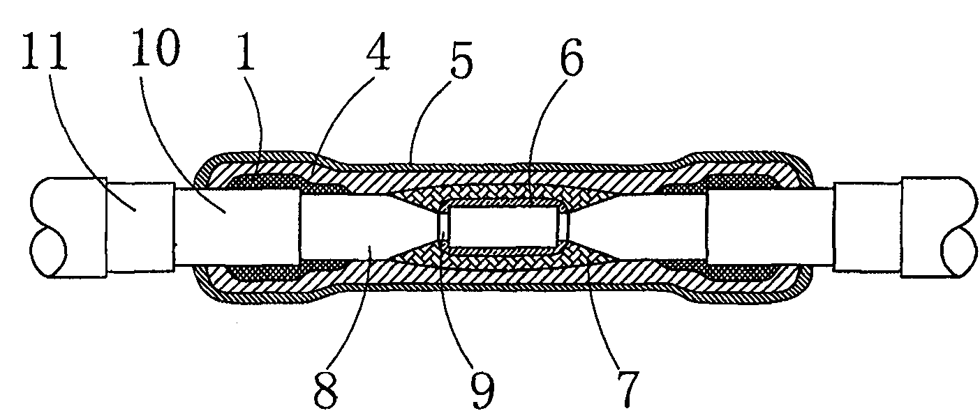
technical field [0001] The invention relates to a cable accessory, in particular to a heat-shrinkable cable intermediate joint composite sleeve used in the cable intermediate joint and a manufacturing method thereof. Background technique [0002] In the transmission line, a long-distance transmission line is usually formed by connecting several cables end to end, and the junction of these cables is called the cable intermediate joint. Such as figure 1 As shown, when connecting cross-linked cables of 35kV and below, the outer semiconducting layer 10 and the insulating layer 8 at the cable connection should be stripped stepwise to expose the core wire 9. After the core wires are connected, the The connection of the wires is wound with a semiconducting tape 6 and an insulating self-adhesive tape 7 in sequence. Because the copper shielding layer 11 of the cable itself and the outer semiconducting layer 10 are cut off at the joint, at the cutoff, it is easy to generate electric...

Claims


Application Information

Patent Timeline
Patent Type & Authority Patents(China)
IPC IPC(8): H02G15/18H01B17/60H01B3/30H01B3/44H01B19/00
Inventor 华国明龙雅民倪昭华王进苏淯钟生良叶桂平丁贵芝
Owner CHANGYUAN GRP
Learn More