
Method for preparing firm flexible printed board

A technology of a rigid-flex printed board and a manufacturing method, which is used in the manufacture of multi-layer circuits and the formation of electrical connection of printed components, etc., can solve the problems of difficult gold plating, poor operability, and poor reliability, and achieves strong repeatability and no Individual differences, the effect of realizing mass production

Inactive Publication Date: 2008-12-24
靖江市杰华网络技术有限公司
View PDF0 Cites 26 Cited by
  • Summary
  • Abstract
  • Description
  • Claims
  • Application Information

AI Technical Summary

Problems solved by technology

This method is limited to making some samples in the development stage of soft and hard boards, and it is impossible to achieve mass production
Moreover, the method of sticking the tape itself has relatively large defects. First, the tape itself may have glue residue. If there is glue left on the gold finger pad on the second and third types of rigid-flex , it is difficult to plate gold in the follow-up gold plating process, which directly leads to quality problems; secondly, in order to provide sufficient mechanical strength, the rigid circuit board has a certain thickness, and the rigid circuit board and the flexible circuit at the edge of the window of the rigid circuit board The board will form a drop step, and the tape will be easily lifted. When the tape is lifted, there will be a gap at the step, and the black hole potion will be poured from this gap, and the toner will still be stuck to the flexible circuit board. Moreover, the sticking and tearing of the tape itself is manual work, which is poor in operability, and the situation of each person's sticking is also different. The reliability is poor, and it cannot adapt to mass production at all.

Method used


Image

  • Method for preparing firm flexible printed board
  • Method for preparing firm flexible printed board
  • Method for preparing firm flexible printed board

Examples


Embodiment Construction

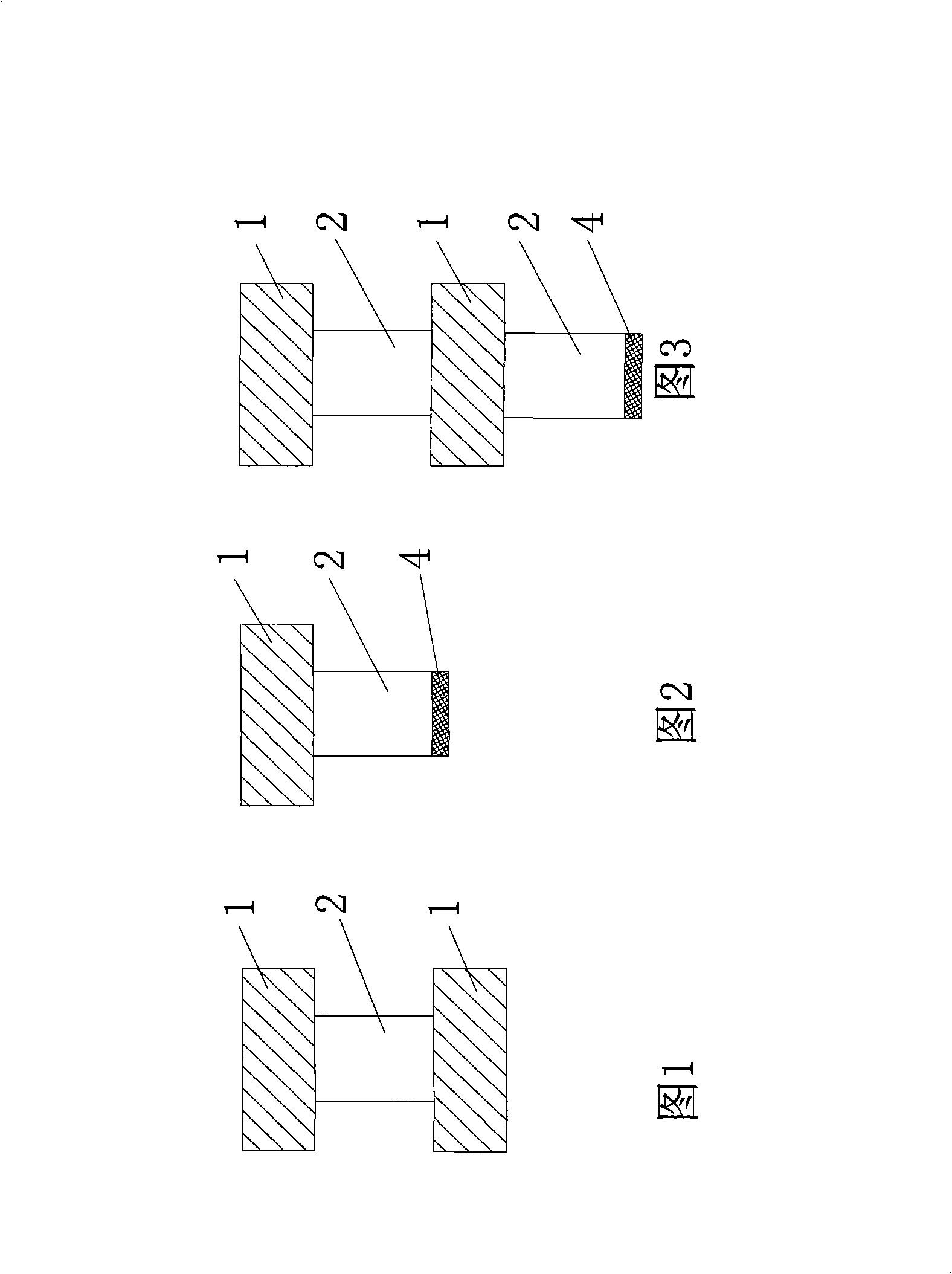
[0033] The present invention will be further described in detail below in conjunction with the specific embodiments and drawings. This specific embodiment is described for the second type of rigid-flex printed boards of four layers, but the method of the present invention can be applied to other types of rigid-flex printed boards equally, and for other layers (such as 6, 8 layers ) Rigid-flex printed boards are also applicable.

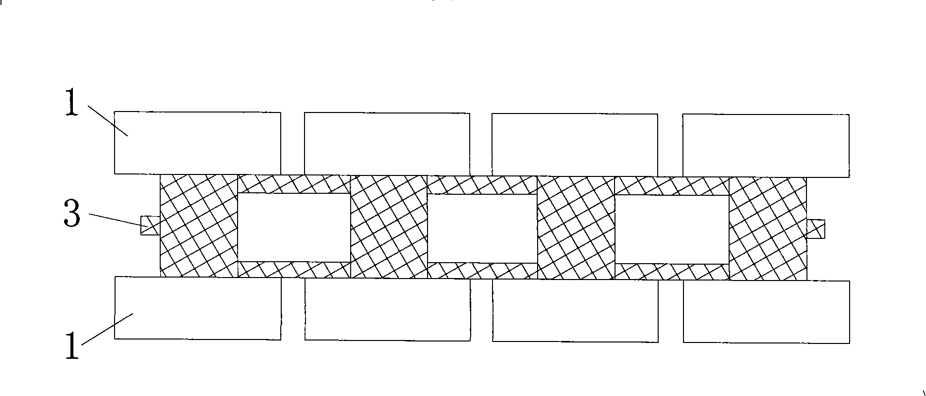
[0034] Such as Figure 7 As shown, a four-layer rigid-flex printed board of the second type includes an outer layer (layer 1 and layer 4) composed of a rigid circuit board 1, and an inner layer composed of a flexible circuit board 2 (layers 2 and 3 ), the line pad 4 on the flexible board (ie the gold finger pad). The circuit board needs to be printed with a peelable mask layer 3 during the manufacturing process of the present invention, and the peelable mask layer 3 will be torn off in the subsequent process. Such as Image 6 with Figure 8 As sh...


PUM


Abstract

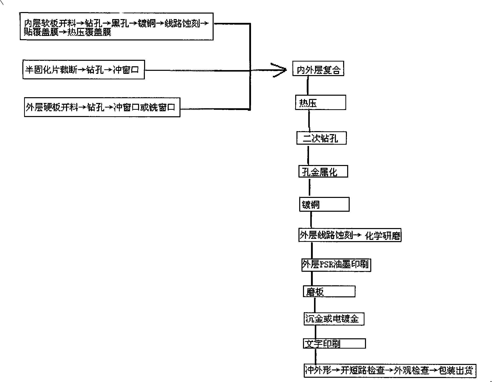
The invention discloses a method for producing rigid and flexible printed circuit boards, and comprises the following steps: a produced flexible circuit board and a produced rigid circuit board bond with each other by using bonding substrate; a second through-hole is drilled on a soft-hard combination area after the flexible circuit board and the rigid circuit board bond; peelable glue is printed and solidified on the exposed flexible circuit board, and then the second through-hole is blackened; the second through-hole and the outer surface of the substrate of the rigid circuit board is coated with copper, and then circuit etching is performed on the outer surface of the substrate of the rigid circuit board; the peelable glue is ripped off, so as to perform the subsequent grinding, welding resistance, gold immersion or electro-gilding technique. Based on the prior equipment in the FPC plant, before the second through-hole on the soft-hard combination area is blackened by the method for producing the rigid and the flexible printed circuit boards, the peelable glue is printed and solidified on the exposed flexible circuit board, thereby preventing carbon powder from being attached to a base film or a cover film of the fixable board in the blackening process, and realizing the protection for the exposed flexible circuit board.

Description

technical field [0001] The invention relates to a method for manufacturing a rigid-flex printed board. Background technique [0002] With the continuous development and innovation of Printed Circuit Board (PCB) and Flexible Printed Circuit Board (FPC) processing technology, Rigid-Flex Printed Circuit Board (Rigid-Flex Printed Circuit Board) came into being. The emergence of rigid-flex printed boards has brought new opportunities to solve the interconnection problem between functional modules of electronic equipment. Rigid-flex printed boards can be folded, bent, and crimped, so that circuits between different planes can be easily connected, and moving parts can also be connected to realize three-dimensional wiring, thereby solving many problems that were originally limited in packaging and improving connection density. , Enhance the reliability of electronic equipment. Moreover, the application of rigid-flexible printed boards to the bottom plate and sub-boards can reduce ...

Claims


Application Information

Patent Timeline
IPC IPC(8): H05K3/46H05K3/42
Inventor 李贤维余婷
Owner 靖江市杰华网络技术有限公司
Learn More