Industrial boiler combustion method

A combustion method and technology of industrial boilers, applied in combustion equipment, lighting and heating equipment, etc., can solve problems such as unsatisfactory effect, high dust concentration, insufficient mixing, etc., to reduce smoke and dust emissions, reduce pollution, and burn quickly Effect

Active Publication Date: 2008-12-31
SHANGHAI TIQIAO TEXTILE & YARN DYEING
View PDF0 Cites 19 Cited by
  • Summary
  • Abstract
  • Description
  • Claims
  • Application Information

AI Technical Summary

Problems solved by technology

[0002] Chain boiler is a furnace type widely used in industrial boilers at present. As shown in Figure 1, it includes boiler furnace C and chain grate B. Fuel coal A enters the boiler and burns in layers on chain grate B. The combustion flue gas flows from The outlet D of the boiler furnace C is discharged. The disadvantage of this kind of boiler is that the mixture with the air i

Method used


Image

  • Industrial boiler combustion method
  • Industrial boiler combustion method
  • Industrial boiler combustion method

Examples


Embodiment 1

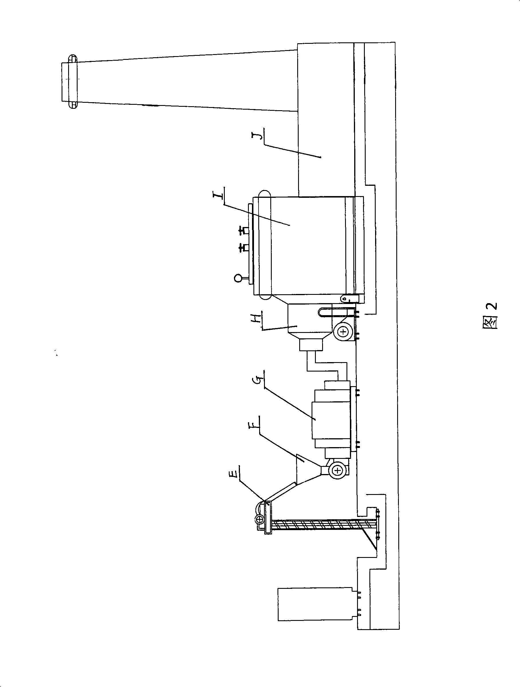
[0038] As shown in Figure 2, it is a schematic diagram of the combustion method of the present invention, and a combustion method of an industrial boiler is,

[0039] One, for old boilers, the method is:

[0040] The first step is to remove the grate at the bottom of the old boiler to become a pure furnace I;

[0041] In the second step, at least one burner H is installed on one side of the pure furnace I;

[0042] In the third step, the pulverized coal E enters the electronic scale G through the coal hopper F and then enters the burner H;

[0043] In the fourth step, the pulverized coal E is mixed with air in the burner H, ignited, intensified combustion, NOx reduction, embers, liquid slag formation, and low NOx emissions. Finally, the clean high-temperature flue gas is sent to the pure furnace I is absorbed and utilized through the flue J;

[0044] Second, for new boilers, the method is:

[0045] The first step is to make a boiler with a pure hearth; the second to fourth...

Embodiment 2

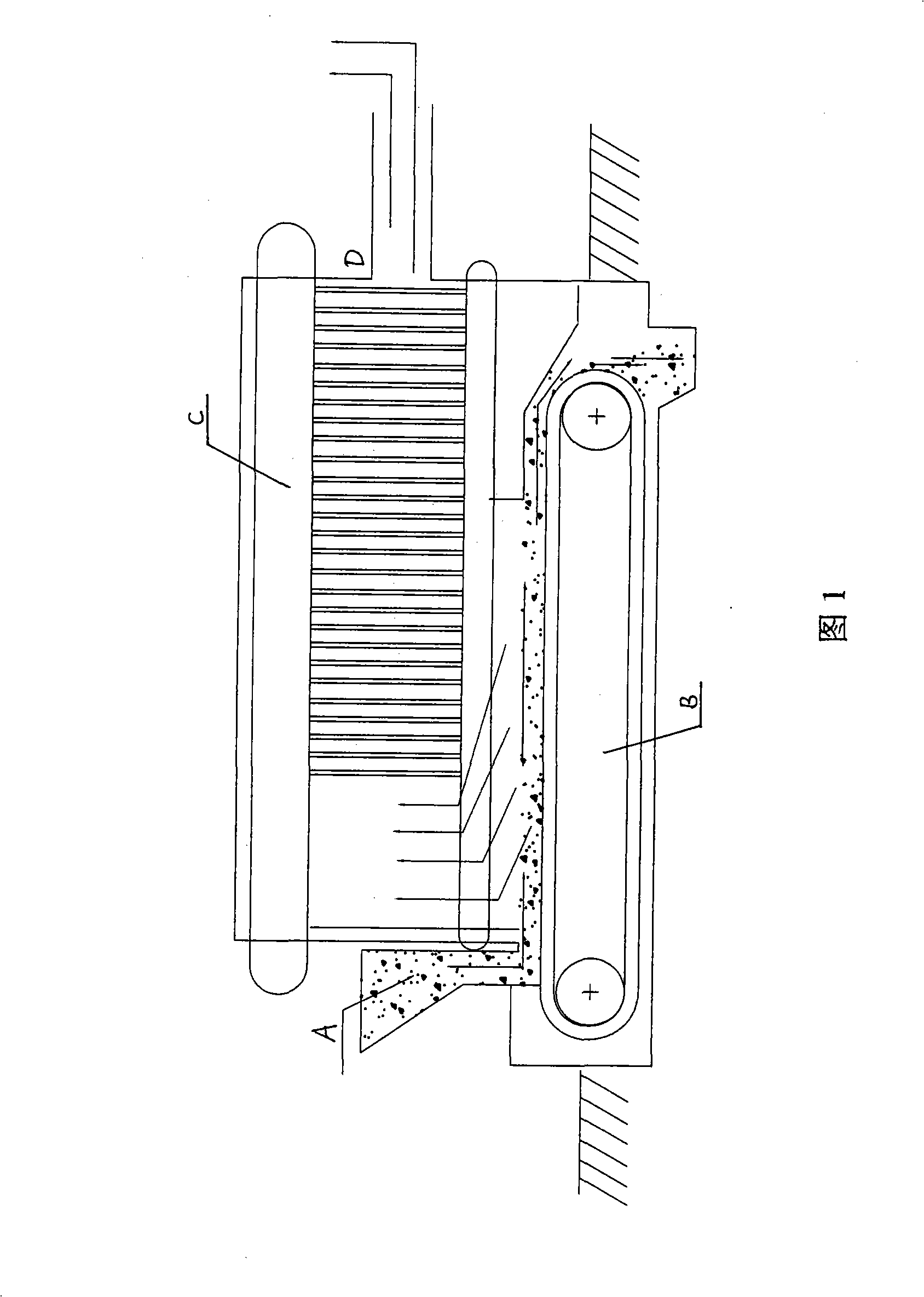
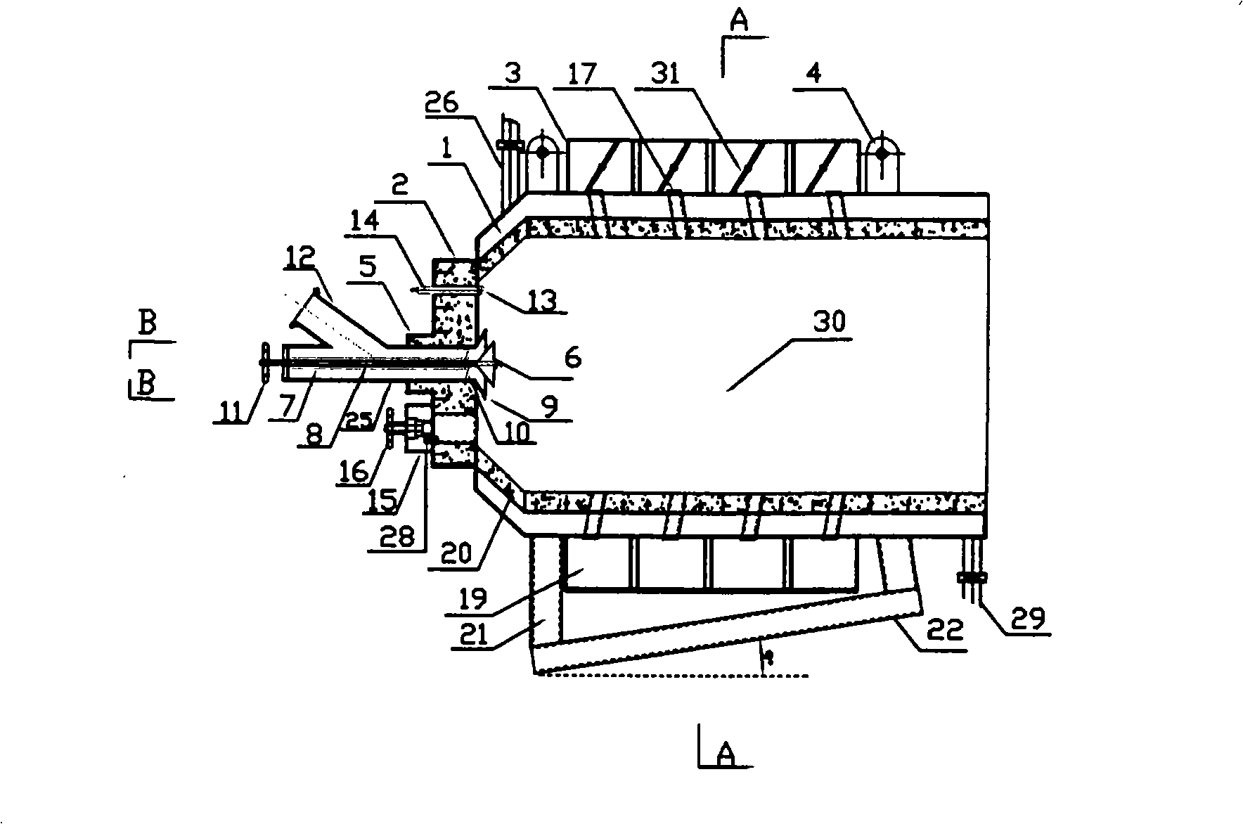
[0054] Taking the 10-ton chain grate steam boiler burner as an example, as shown in Figures 7 and 8, it is a schematic structural diagram of an air-cooled low-NOx liquid slagging double-swirl pulverized coal burner. The low NOx liquid slagging double-swirl pulverized coal burner is composed of an adjustable injection device 5 and a combustion chamber 30: the adjustable injection device 5 is the same as that of Embodiment 1, and the only difference between the combustion chamber 30 is the combustion chamber shell Secondary air heat exchange fins 33 are arranged between 20 and secondary air chamber 19, and other parts are the same as in Embodiment 1.

[0055] The second example of the present invention: reform the boiler, install the air-cooled low NOx liquid slagging double-swirl pulverized coal burner, the reformed boiler is the SZL10-1.25-AII chain grate boiler produced by Jiangsu Nantong Boiler Factory, and the boiler is 05 years old Factory put into operation, boiler test t...


PUM


Abstract

The invention relates to a combusting method for an industrial boiler, which is characterized in that an old style boiler adopts the method that a fire grate at the bottom of the old style boiler is removed, to form a pure furnace chamber I; at least one combustor H is installed at one side of the pure furnace chamber I; coal powder E enters into the combustor H after entering into an electronic scale G through a coal scuttle F; the coal powder E performs the complete process of mixture with the air, firing, reinforced combustion, deoxidization of NOx, combustion into ash, liquid slugging and low NOx discharging inside the combustor H, and finally the pure high temperature fume is transmitted to the pure furnace chamber I and absorbed and utilized through a smoke flue J; a novel boiler adopts the method that a boiler with a pure furnace chamber is manufactured; the second to the forth steps are identical to the combusting method of the old style boiler. The combusting method has advantages that the combustion is sufficient, the effects of energy conservation and discharge reducing are remarkable, the pollution is reduced, and the service life is prolonged.

Description

technical field [0001] The invention relates to a combustion method of an industrial boiler, which is applicable to combustion devices for various industrial productions such as 2-35 ton steam and hot water boilers, kilns, forging, steelmaking, road and bridge mixing stations and cold aggregate heating, etc. , belongs to the technical field of pulverized coal burners. Background technique [0002] Chain boiler is a furnace type widely used in industrial boilers at present. As shown in Figure 1, it includes boiler furnace C and chain grate B. Fuel coal A enters the boiler and burns in layers on chain grate B. The combustion flue gas flows from The outlet D of the boiler furnace C is discharged. The disadvantage of this kind of boiler is that the mixture with the air is not sufficient during combustion, resulting in incomplete combustion, low combustion rate, and q 4 Large loss, exhaust smoke contains NOx, SO 2 , High dust concentration, and pollute the environment. In order...

Claims


Application Information

Patent Timeline
IPC IPC(8): F23C9/06
Inventor 郑雯平潘玉明潘雪明
Owner SHANGHAI TIQIAO TEXTILE & YARN DYEING
Why Eureka
Try Eureka