Thermal batch reactor with removable susceptors

A batch processing and detachable technology, applied in the field of batch processing chamber, can solve the problems of high processing cost and low output

Inactive Publication Date: 2009-01-07
APPLIED MATERIALS INC
View PDF2 Cites 17 Cited by
  • Summary
  • Abstract
  • Description
  • Claims
  • Application Information

AI Technical Summary

Problems solved by technology

However, single substrate processing chambers typically have lower throughput and higher processing costs per substrate than batch chambers

Method used


Image

  • Thermal batch reactor with removable susceptors
  • Thermal batch reactor with removable susceptors
  • Thermal batch reactor with removable susceptors

Examples


Embodiment Construction

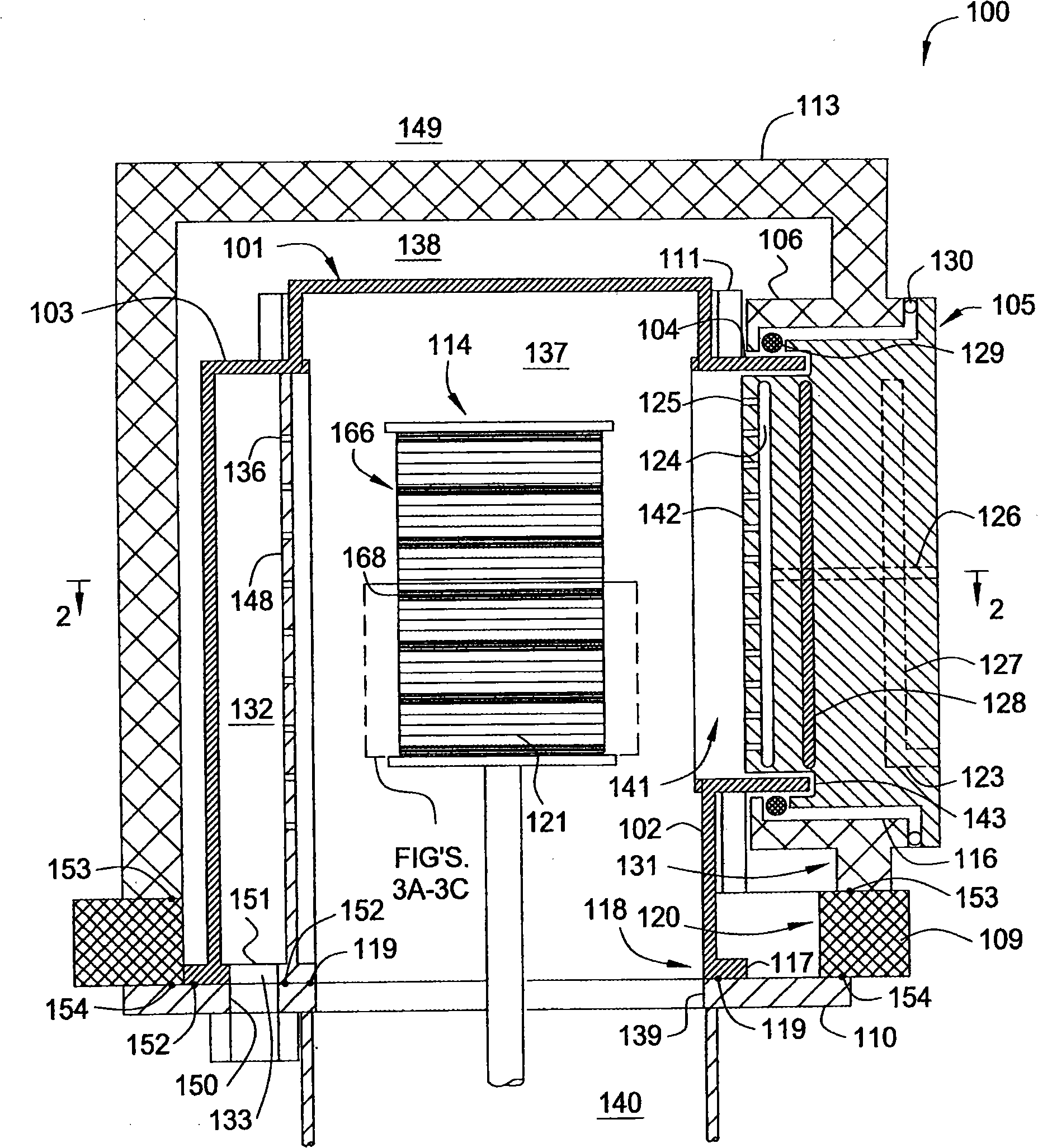
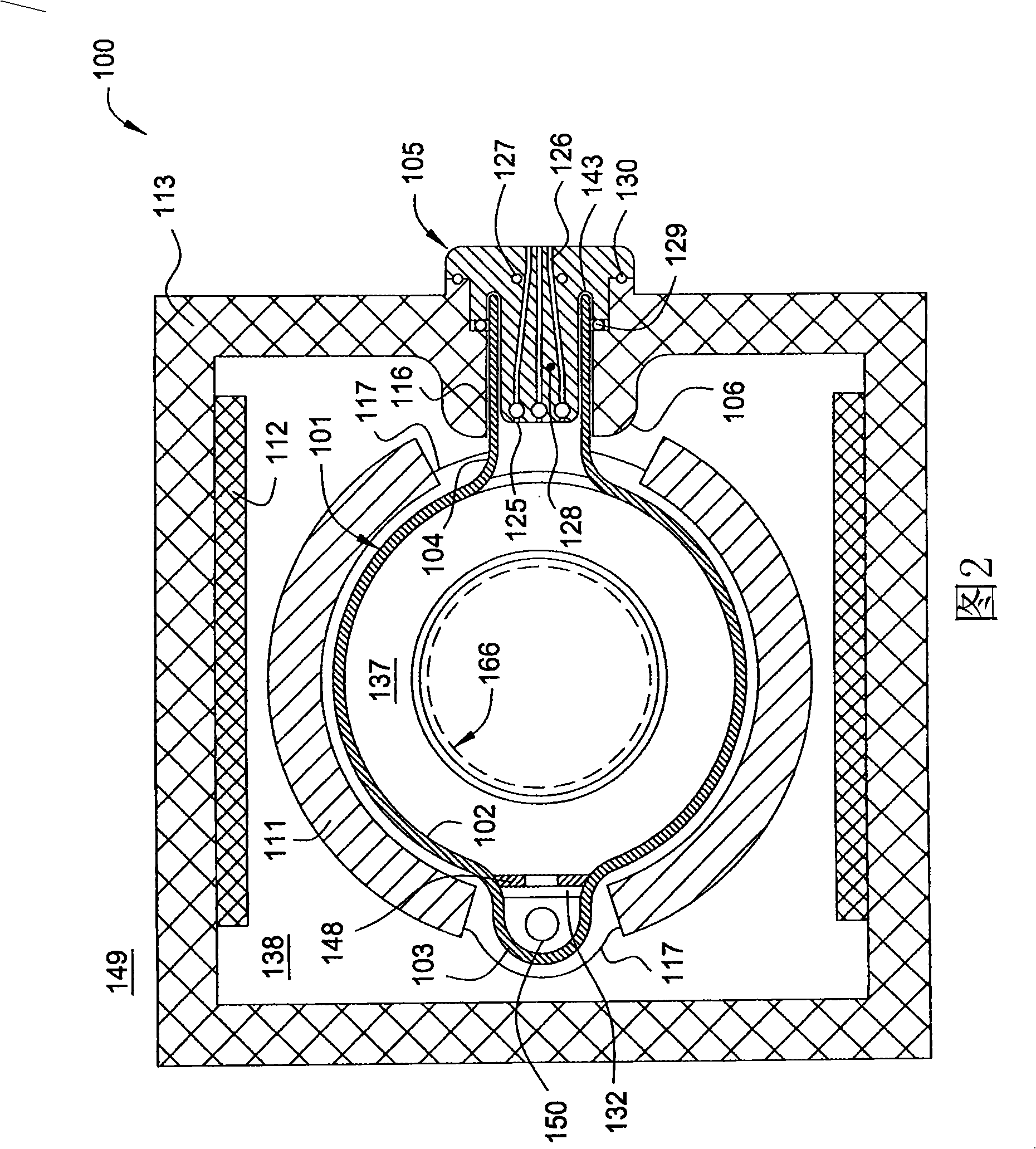
[0018] The present invention generally provides a method and apparatus for a batch processing chamber that provides uniform heating and uniform gas flow for multiple substrates disposed in a quartz reaction chamber.

[0019] The batch processing chambers described herein can also be used to increase substrate throughput when used in chemical vapor deposition (CVD) and atomic layer deposition (ALD) processes with low deposition rates. For example, the chamber of the present invention can be used to deposit silicon-containing films and hafnium-containing films, such as hafnium oxide or hafnium silicate (ie, hafnium silicon oxide), using an ALD-type process. Due to the slow deposition rate of hafnium oxide or hafnium silicate, eg, it may take about 200 minutes to deposit 30 Angstroms, this disproportionately long process step is advantageously performed in the batch processing chamber of the present invention.

[0020] figure 1 is a schematic side view of the batch processing ch...


PUM

PropertyMeasurementUnit
thicknessaaaaaaaaaa
diameteraaaaaaaaaa
diameteraaaaaaaaaa

Abstract

An apparatus and method for uniform heating and gas flow in a batch processing chamber are provided. The apparatus includes a quartz chamber body, removable heater blocks which surround the quartz chamber body, an inject assembly coupled to one side of the quartz chamber body, and a substrate boat having removable susceptors. In one embodiment, the boat may be configured with a plurality of susceptors to control substrate heating during batch processing.

Description

technical field [0001] Embodiments of the invention generally relate to a batch processing chamber. More specifically, embodiments of the present invention relate to methods and apparatus for uniform heating of substrates and uniform delivery of gases in batch processing chambers. Background technique [0002] The term batch processing generally refers to the simultaneous processing of two or more substrates in one reactor. There are several advantages to batching substrates. Batch processing can increase the throughput of a substrate processing system by executing process recipe steps for a disproportionate amount of time compared to other process recipe steps of the substrate processing sequence. For longer menu steps, the use of batch processing effectively reduces the processing time per substrate. Another advantage of batch processing can be seen in some processing steps such as ALD (Atomic Layer Deposition) and CVD (Chemical Vapor Deposition) that use expensive prec...

Claims


Application Information

Patent Timeline
Patent Type & Authority Applications(China)
IPC IPC(8): C23C16/44C23C16/46C23C16/455H01L21/00
CPCH01L21/67306C23C16/46H01L21/67309Y10T428/13C23C16/4586H01L21/00H01L21/02
Inventor 尼尔·梅里约瑟夫·尤多夫斯凯
Owner APPLIED MATERIALS INC
Why Eureka
Try Eureka