Inner layer granule reinforced cylinder sleeve and method of manufacture

A technology of particle enhancement and manufacturing method, applied in the direction of cylinder, cylinder head, machine/engine, etc., can solve the problems of affecting the service life of cylinder liner, long time for melting silicon particles, and easy peeling of reinforcement layer, saving raw materials and saving energy. The effect of eliminating the processing steps and lowering the manufacturing cost

Inactive Publication Date: 2009-01-07
CHONGQING UNIV
View PDF0 Cites 29 Cited by
  • Summary
  • Abstract
  • Description
  • Claims
  • Application Information

AI Technical Summary

Problems solved by technology

This method requires a laser and its control instruments and equipment, and the process is complicated; the laser is a point light source, so it takes a long time to melt the silicon particles and the production efficiency is l

Method used


Image

  • Inner layer granule reinforced cylinder sleeve and method of manufacture

Examples


Embodiment 1

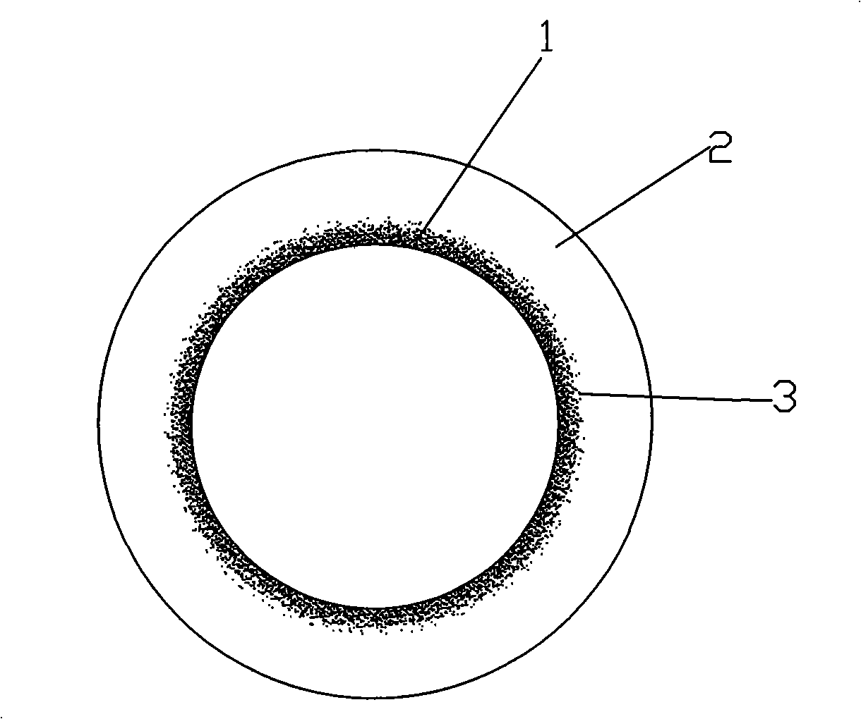
[0023] The reinforcement layer is located in the primary crystal Si and Mg on the inner surface of the cylinder liner 2 The Si reinforced particles are 10% by volume, and the primary Si and Mg 2 Among the mixed particles of Si, the primary crystal Si accounts for 20% by volume, and the particle size of the primary crystal Si is 20-120 μm, Mg 2 The particle size of Si is 20-40 μm.

Embodiment 2

[0025] The reinforcement layer is located in the primary crystal Si and Mg on the inner surface of the cylinder liner 2 The Si reinforcement particles are 20% by volume, and the volume percentage of the reinforcement particles in this embodiment makes the mechanical properties and wear resistance of the cylinder liner better than that of Embodiment 1; in primary Si and Mg 2 Among the mixed particles of Si, the primary crystal Si accounts for 50% by volume, and the particle size of the primary crystal Si is 20-120 μm, Mg 2 The particle size of Si is 20-40 μm.

Embodiment 3

[0027] The reinforcement layer is located in the primary crystal Si and Mg on the inner surface of the cylinder liner 2 The Si reinforcement particles are 35% by volume, and the volume percentage of the reinforcement particles in this embodiment makes the mechanical properties and wear resistance of the cylinder liner better than that of Example 2; in primary Si and Mg 2 Among the mixed particles of Si, primary Si accounts for 35% by volume, and the particle size of primary Si is 20-120 μm, Mg 2 The particle size of Si is 20-40 μm, and the volume percentage of primary Si in the reinforced particles of this embodiment makes the mechanical performance and wear resistance of the cylinder liner better than that of Embodiment 2.


PUM

PropertyMeasurementUnit
Particle sizeaaaaaaaaaa
Thicknessaaaaaaaaaa

Abstract

The present invention discloses a reinforced internal layer particle cylinder sleeve and a manufacturing method thereof. The reinforced internal layer particle cylinder sleeve comprises a cylinder sleeve substrate which comprises a radial inner reinforced layer and an outer non-reinforced layer. The reinforced layer consists of reinforced particles distributed in the cylinder body substrate. The reinforced layer and the non-reinforced layer are combined by an alloy combined transition layer. The transition of the reinforced layer and the non-reinforced layer of the present invention is uniform, slow, stable and firm, thereby prolonging the service life of the cylinder sleeve; the cylinder sleeve has light weight, low porosity factor and good mechanical performance and thermal performance and improves the working efficiency of an engine; the manufacturing method has simple technical process and high production efficiency; the content of the reinforced particles in the non-reinforced layer is zero, thereby increasing the wearability of the inner layer and also causing no influence on the integral mechanical performance of the cylinder sleeve, such as the intensity of tension, and the like; the cylinder sleeve uses a centrifugal casting method to form an inner layer particles segregated roughcast and then is made by the heat treatment and mechanical cutting, processing and manufacturing of the roughcast.

Description

technical field [0001] The invention relates to an engine cylinder component, in particular to an inner particle reinforced cylinder liner and a manufacturing method thereof. Background technique [0002] The cylinder liner is an important part of the internal combustion engine. The mechanical and thermal properties of the cylinder liner have an important impact on the working efficiency, service life and working state of the engine. The traditional engine cylinder liner material is mainly alloy wear-resistant cast iron or steel plate. With the further strengthening of the awareness of energy saving and environmental protection, the requirements for weight reduction of automobiles are getting higher and higher. Then there is the emergence of cylinder liners made of materials such as aluminum alloys with low density. In order to increase the mechanical properties and thermal In terms of performance, there are two methods of manufacturing aluminum alloy cylinder liners in the...

Claims


Application Information

Patent Timeline
IPC IPC(8): F02F1/00B22D15/02B22D13/00
Inventor 刘昌明翟彦博谢勇王开
Owner CHONGQING UNIV
Why Eureka
Try Eureka