Resetting and calibration of detector for visible and infrared composite light path light axis parallelism

A technology of parallel optical axis and complex light, which is applied in the field of optical detectors to achieve the effects of high detection accuracy and convenient installation and adjustment

Inactive Publication Date: 2009-01-07
INST OF OPTICS & ELECTRONICS - CHINESE ACAD OF SCI
View PDF0 Cites 27 Cited by
  • Summary
  • Abstract
  • Description
  • Claims
  • Application Information

AI Technical Summary

Problems solved by technology

However, the above technologies can only provide parallel light waves of a single band for the installation and calibration of optical instruments or optical systems working in a single band. There

Method used


Image

  • Resetting and calibration of detector for visible and infrared composite light path light axis parallelism
  • Resetting and calibration of detector for visible and infrared composite light path light axis parallelism
  • Resetting and calibration of detector for visible and infrared composite light path light axis parallelism

Examples


Embodiment Construction

[0022] The present invention will be described in detail below in conjunction with the accompanying drawings and specific embodiments.

[0023] This embodiment introduces a method for installing, adjusting and calibrating an optical axis parallelism detector for a combined visible and infrared optical path. The specific steps are as follows:

[0024] (1) Coarse adjustment of the instrument;

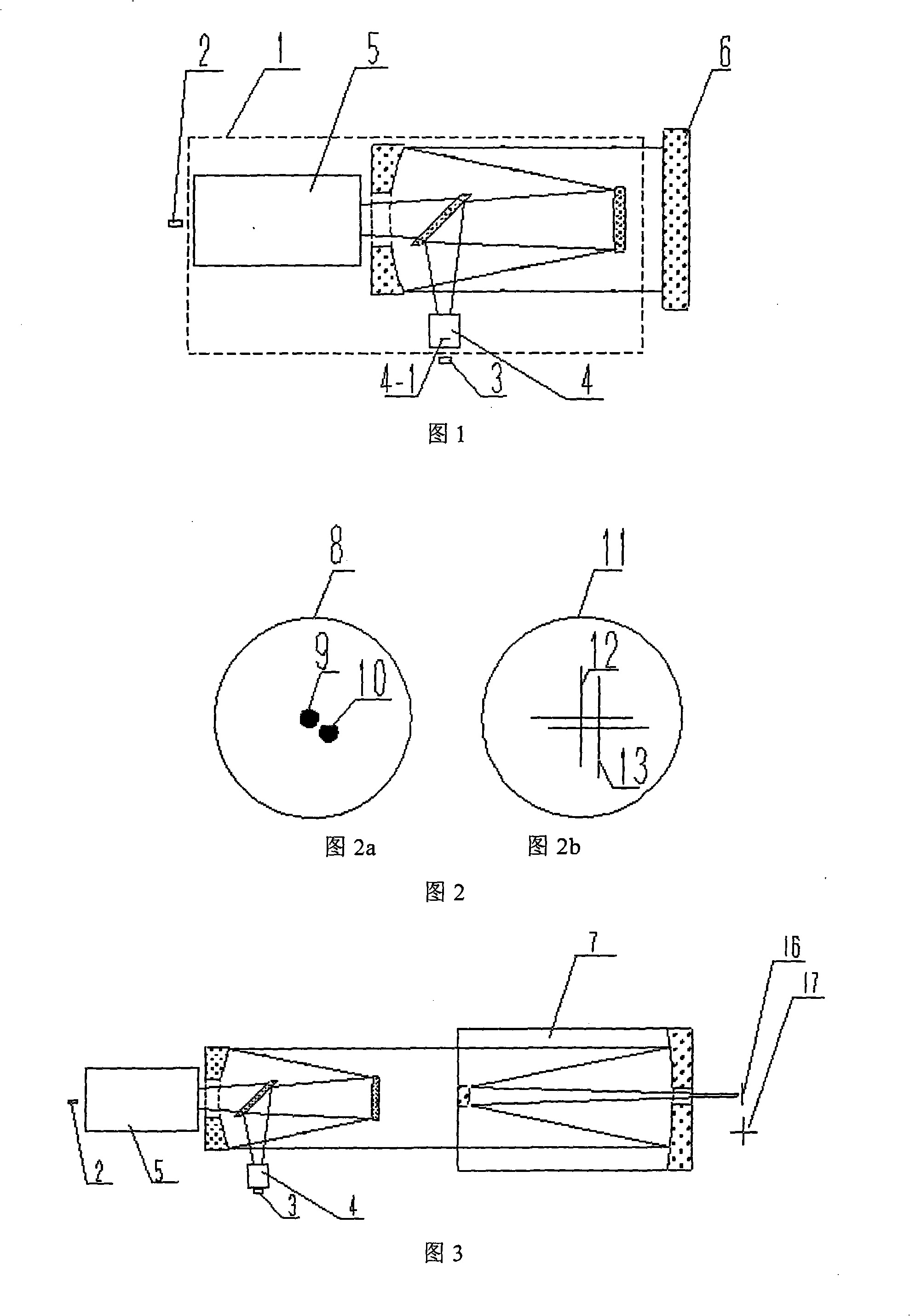
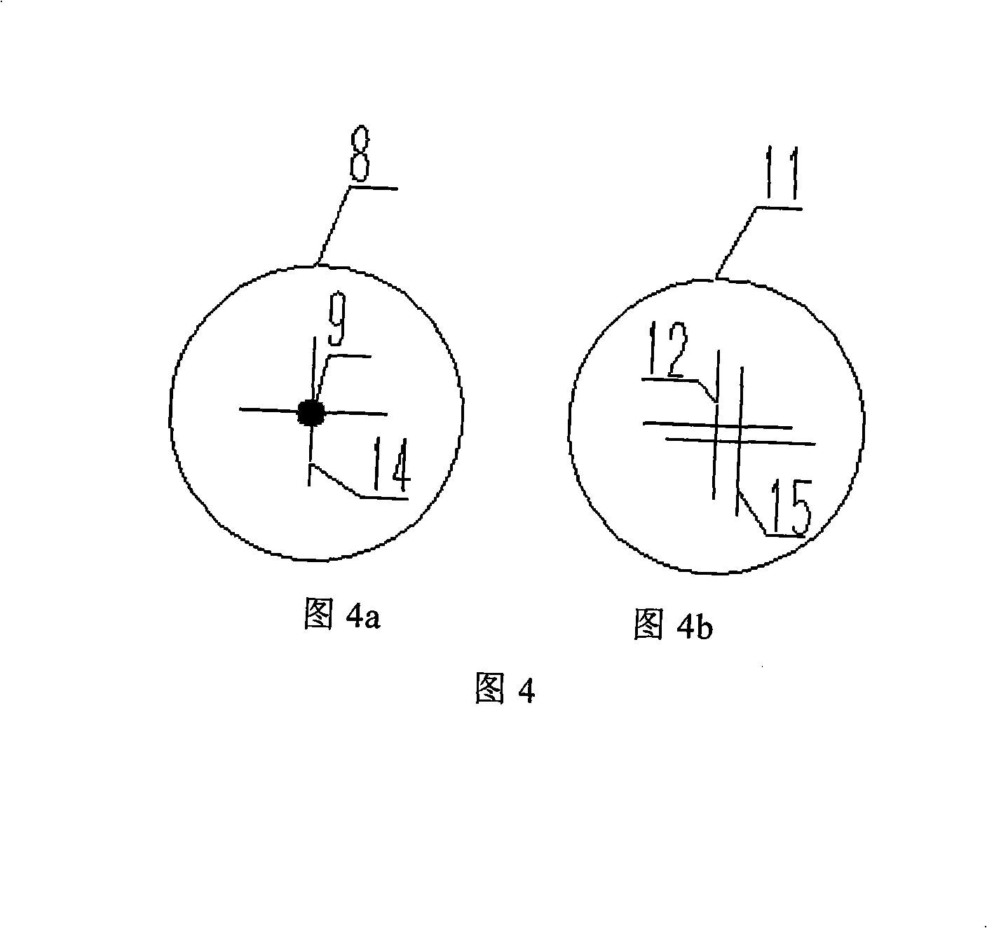
[0025] As shown in Figure 1, place a visible crosshair 4-1 on the focal plane of the visible light part 4 of the visible and infrared compound optical path optical axis parallelism detector 1, and then place a visible light CCD3; An infrared CCD2 is placed behind the focal plane of the infrared part 5 of the detector 1, and a standard flat mirror 6 is placed behind the visible and infrared compound optical path optical axis parallelism detector 1, and the inclination and pitch of the standard flat mirror 6 are adjusted so that the visible light CCD3 can See the image 12 of the outgoing v...


PUM

PropertyMeasurementUnit
Diameteraaaaaaaaaa
Fever temperatureaaaaaaaaaa

Abstract

The invention relates to a metnod for the assembling adjusting and standardization of a visible-infrared light compound optical path optical axis parallelism detector, which is characterized in that: placing a standard plane mirror on the back of the visible-infrared light compound optical path optical axis parallelism detector to roughly adjust the detector; placing a reflecting collimator and a high-temperature cross wire respectively on the back and the focal plane of the visible-infrared light compound optical path optical axis parallelism detector; electrifying the high-temperature cross wire to emit visible light wave and infrared light wave; adjusting the reflecting collimator to ensure the complete coincidence of the emitting visible cross wire image and the visible light image of the high-temperature cross wire on visible light CCD; adjusting the infrared part of the visible-infrared light compound optical path optical axis parallelism detector to ensure the completer coincidence of the infrared laser spot on infrared CCD and the infrared image of the high-temperature cross wire; standardizing the detector and calculating the optical axis parallelism difference between the visible light wave and the infrared light wave after the visible light and the infrared light gather in the same optical system with the help of software processing algorithm. The method has the advantages of convenient assembling adjustment and high precision.

Description

technical field [0001] The invention relates to an optical detector, in particular to the installation, adjustment and calibration of a visible and infrared compound light path optical axis parallelism detector. Background technique [0002] Visible and infrared compound light path optical axis parallelism detector is used to detect the parallelism error between the visible light path optical axis and the infrared light path optical axis of the optical instrument or optical system working on the visible and infrared compound light path, and the allowable error of parallelism is several arcseconds, so parallel visible and infrared composite optical path light waves are needed to complete the adjustment and calibration of this type of instrument. For the adjustment and calibration methods of optical instruments or optical systems working in a single wavelength band, the technology is quite mature at present: the adjustment and calibration of optical instruments or optical syst...

Claims


Application Information

Patent Timeline
IPC IPC(8): G01B11/26G01B11/27G01M11/02
Inventor 景洪伟杨文志吴时彬曹学东
Owner INST OF OPTICS & ELECTRONICS - CHINESE ACAD OF SCI
Why Eureka
Try Eureka