Capillary pipe optical fibre light forceps and its manufacture method

A technology of optical fiber optical tweezers and a manufacturing method, applied in the field of optical tweezers, can solve problems such as low efficiency of manipulation and assembly

Inactive Publication Date: 2009-01-07
HARBIN ENG UNIV
View PDF4 Cites 36 Cited by
  • Summary
  • Abstract
  • Description
  • Claims
  • Application Information

AI Technical Summary

Problems solved by technology

Low manipulation and assembly efficiency for large nu

Method used


Image

  • Capillary pipe optical fibre light forceps and its manufacture method
  • Capillary pipe optical fibre light forceps and its manufacture method
  • Capillary pipe optical fibre light forceps and its manufacture method

Examples


Embodiment ( 1

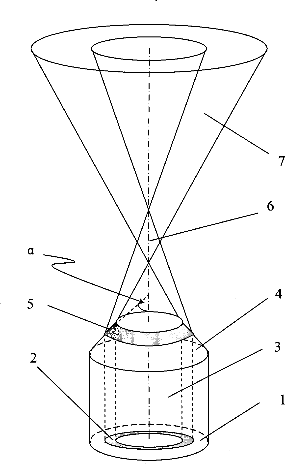
[0029] figure 2 An implementation method of the tapered fiber optical tweezers of the present invention is given. Its implementation process is as follows:

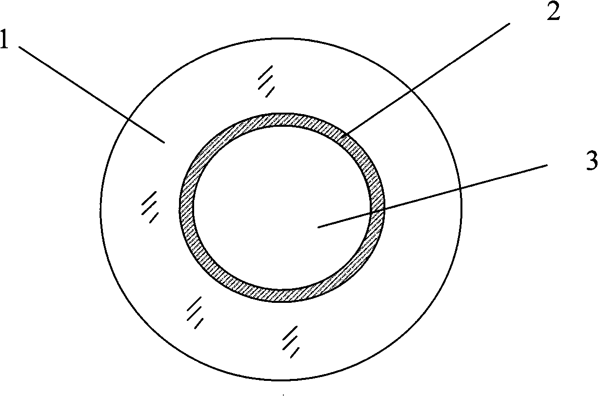
[0030] Step 1, Cone Grinding: Take a section Figure 1-a In the illustrated ring-core capillary fiber, the waveguide layer of the fiber is located on the inner wall of the capillary. With the aid of the bare fiber end grinding system, one end is ground into a figure 2 In the shape of the cone shown, in order to ensure that the outgoing light can form intersecting cone beams after being refracted by the cone surface, the half-cone angle α is controlled at π / 2-arcsin(n liquid / n core )core =1.4868, cladding refractive index n cladding =1.4571, and the liquid refractive index n where the fiber optical tweezers are located water = 1.333, the range of the half-cone angle should be controlled between 26.3° and 80°.

[0031] Step 2, cone polishing: put the above-mentioned ground optical fiber cone in the bare optical fi...

Embodiment ( 2

[0036] image 3 Another implementation method of optical tweezers with a ring-core capillary tube provided by the present invention is given. Its implementation process is as follows:

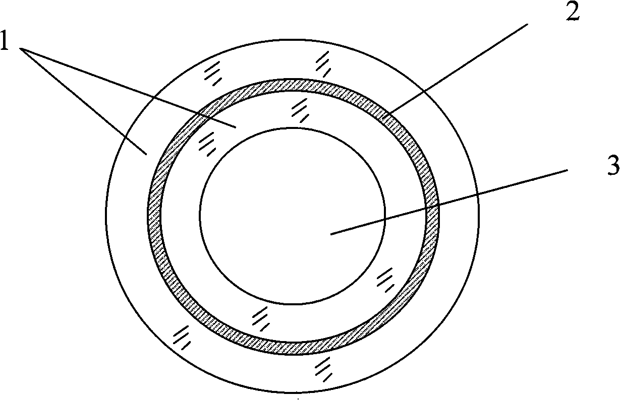
[0037] Step 1, Cone Grinding: Take a section Figure 1-b The ring-core capillary fiber shown has one end ground to a shape such as image 3 In the shape of the frustum of the cone shown, in order to ensure that the outgoing light can form total internal reflection light after passing through the conical surface 4 of the frustum of the cone, and refracted by the top surface of the frustum of the cone to form intersecting conical beams, the half-cone angle α should be controlled at 0liquid / n core )In the range. For the core refractive index n core =1.4868, cladding refractive index n cladding =1.4571, and the liquid refractive index n where the fiber optical tweezers are located water = 1.333, the range of the half-cone angle α should be controlled between 10° and 26.3°.

[0038] Step 2...


PUM


Abstract

The invention provides a capillary fiber optical tweezers and a manufacturing method thereof. One end of the hollow capillary fiber with an annular core layer is processed with a cone which causes the emergent light to form an annular pyramidal decussation light field; a small hole is opened on one side of the middle of the hollow capillary optical fiber with the annular core layer; the small hole is connected with a barometric pressure adjusting device and the other end of the hollow capillary optical fiber with the annular core layer is welded with a standard solid optical fiber; the standard solid optical fiber and the hollow capillary optical fiber with the annular core layer are integrated into a whole by drawing the welding position into a conical transition region. In the capillary fiber optical tweezers of the invention, the capillary provides a storage location for micro particles; on one hand, the captured micro particles can be stored in the capillary through the micro negative pressure absorption function in the capillary; on the other hand, the micro particles can be supplied to a fiber-end tweezers through micro positive pressure, thus realizing the operation of continuous assembly of a large amount of micro particles.

Description

(1) Technical field [0001] The invention relates to an optical tweezers, in particular to an optical tweezers based on a ring-core capillary fiber. The invention also relates to a preparation method of optical tweezers. (2) Background technology [0002] Optical tweezers are tools that use the gradient force and light scattering force of light intensity distribution to capture and manipulate tiny particles. Since 1986, Askin [A.Ashkin, J.M.Dziedzic, J.E.Bjorkholm, and S.Chu, Observation of a single-beam gradient force optical trap for dielectric particles, Opt.Lett.11, 288-290, 1986] put single-beam laser After the introduction of a high numerical aperture objective lens to form a three-dimensional optical potential well and realize the three-dimensional space control of particles, the optical tweezers technology has rapidly developed into an important research technology, and has promoted the rapid development of several interdisciplinary fields. For example, it has been ...

Claims


Application Information

Patent Timeline
IPC IPC(8): G02B6/255G02B6/02G01N15/00G01N37/00G21K1/00
Inventor 苑立波杨军张涛耿涛戴强田凤军
Owner HARBIN ENG UNIV
Why Eureka
Try Eureka