
Finger cutter type helical bevel gear processing device

A processing device and milling cutter technology, which is applied in the direction of driving device, feeding device, metal processing equipment, etc., can solve the problems of many adjustment links, troublesome operation process, and many transmission parts, and achieve simple adjustment, simple structure, and short transmission chain Effect

Inactive Publication Date: 2009-01-14
洛阳科锐机电设备有限公司 +1
View PDF0 Cites 7 Cited by
  • Summary
  • Abstract
  • Description
  • Claims
  • Application Information

AI Technical Summary

Problems solved by technology

This type of cutter head type CNC milling machine needs six-axis linkage during processing. There are many transmission parts and complex linkage relations. Therefore, the structure is complex, there are many adjustment links, and the operation process is troublesome, which directly affects the productivity and processing quality of the gear. In addition, due to the machine tool Space, machine rigidity, cutter head material performance, and various limitations of processing technology make it impossible for the specification of disc milling cutter to expand infinitely with the expansion of gear specifications. The processing range of cutter head CNC milling machine is limited especially when processing large gears. Severe limitations on disk size

Method used


Image

  • Finger cutter type helical bevel gear processing device
  • Finger cutter type helical bevel gear processing device
  • Finger cutter type helical bevel gear processing device

Examples


Embodiment Construction

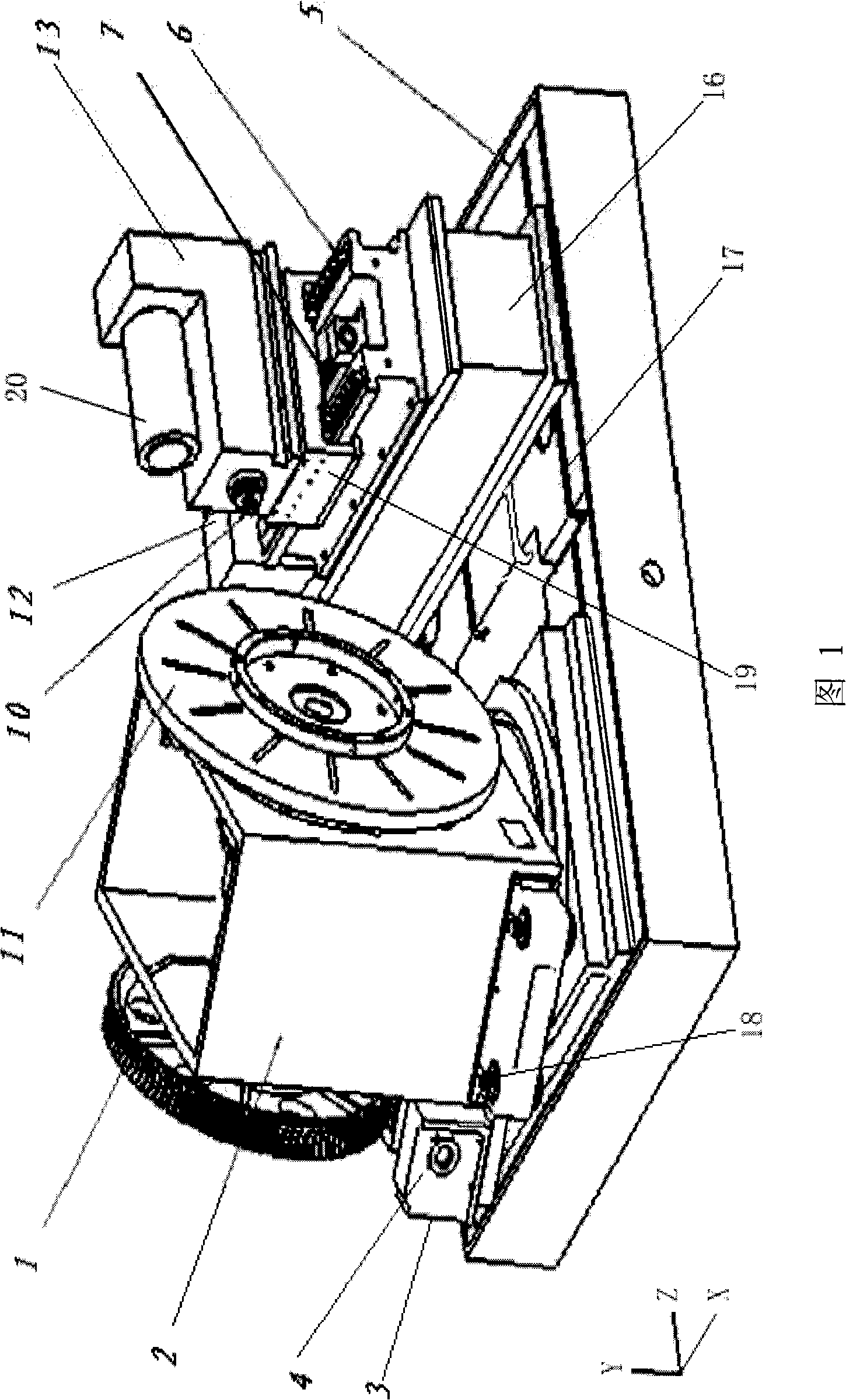
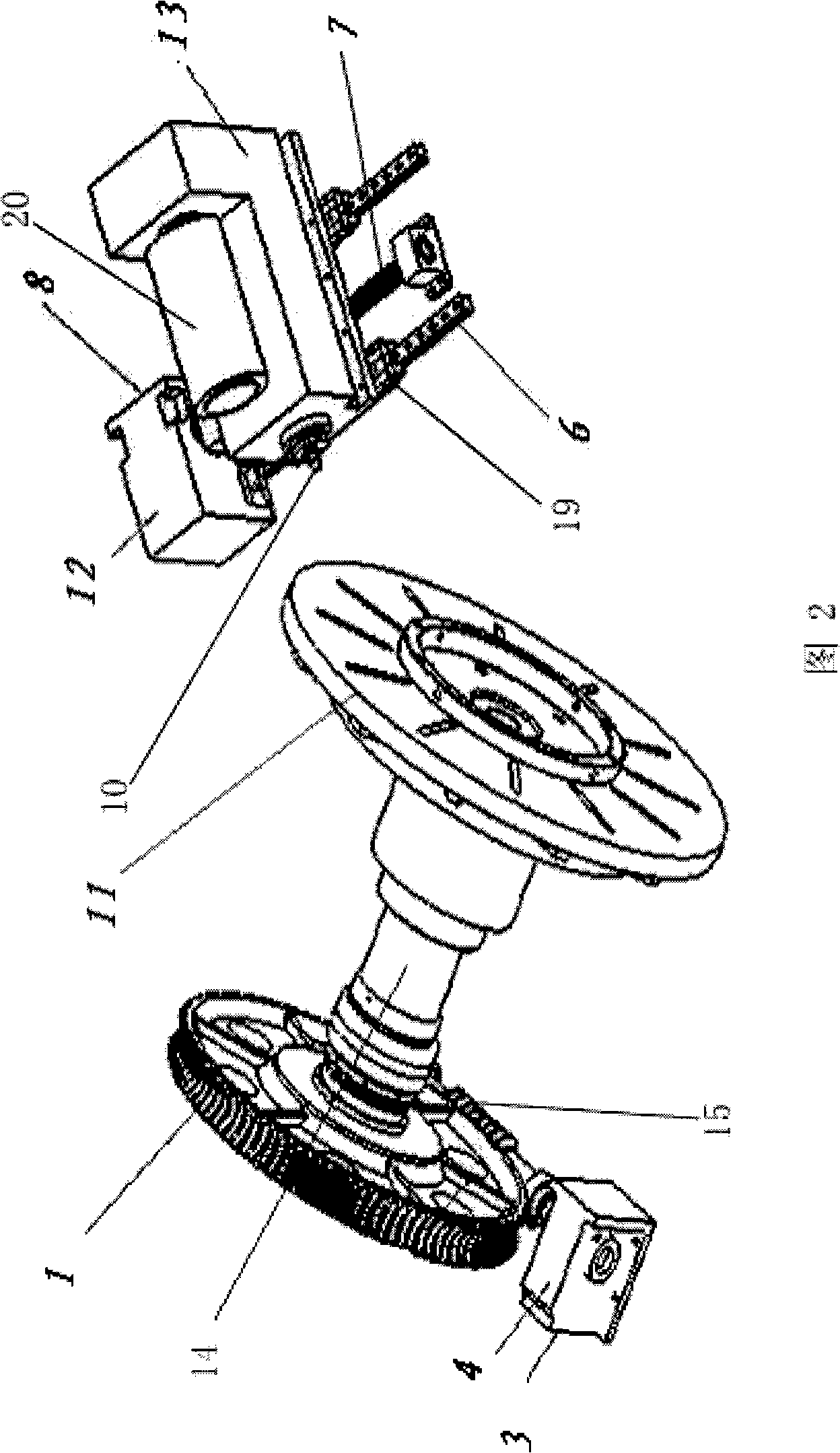
[0014] As shown in Fig. 1 and Fig. 2, the milling machine of the present invention comprises a bed 5, and the both sides of the bed 5 are respectively equipped with a workpiece box 2 and a tool base 16, and the workpiece box 2 is rotatably assembled on the bed 5, and the workpiece box 2 is The rotating shaft around is the vertical Y axis. The workpiece case 2 is provided with bolts 18 for fixed positioning with the bed 5. The workpiece case 2 is equipped with a workpiece main shaft 14 for rotation. Outside the front and rear case surfaces, one end of the workpiece spindle 14 is fixedly connected with the workpiece face plate 11 for fixing the workpiece on the outside of the front case surface of the workpiece case 2, and the other end of the workpiece spindle 14 is fixed with a worm gear on the outside of the workpiece case 2 rear case surface. 1. A worm 15 connected to the worm wheel 1 is provided under the worm wheel 1. One end of the worm 15 is connected to the reducer 4 fix...


PUM


Abstract

The invention discloses a finger-like milling cutter type machining device of spiral bevel gear comprising a machine body (5). The two sides of the body (5) are respectively provided with a space-adjustable workpiece box component and a cutting tool box component. The workpiece box component comprises a workpiece box (2), a workpiece spindle (14) and a driving mechanism for the workpiece spindle. The cutting tool box component comprises a spindle of cutting tool for driving the finger-like milling cutter to rotate and a driving mechanism of the spindle of cutting tool. The workpiece box (2) rotates around the vertical axis Y and is positioned on the machine body (5). The workpiece box (2) is provided with a positioning device for fixing and positioning the machine body (5). The cutting tool box also comprises a cutting tool base (16) which is positioned on the machine body (5), and a cutting tool feeding skid (19) which is movably positioned a X-directional straight guide rail (6) on the cutting tool base (6). The cutting tool spindle is positioned on the cutting tool feeding skid (19) which connects the feed driving mechanism. The finger-like milling cutter type machining device of spiral bevel gear has the advantages of short transmission chain, not requiring the mechanical transmission, high accuracy and good flexibility of program control.

Description

technical field [0001] The invention relates to a numerical control processing equipment for gears, in particular to a spiral bevel gear processing device using a finger milling cutter. Background technique [0002] The existing CNC milling machine for processing spiral bevel gears is a cutter head type CNC milling machine, and the patent No. is 03118143 invention patent: A kind of this type of CNC milling machine is disclosed in the six-dimensional processing device for spiral bevel gears. The workpiece box, the tool box and the driving equipment of the two boxes, the tool used is a disc milling cutter, the driving equipment of the workpiece box and the tool box is: linear guide rails in the three directions of X, Y, and Z and three directions of A, B, and C. Rotating shafts in three directions, through the computer can control the movement of the three linear guides X, Y, and Z and the rotation of the three axes A, B, and C to realize the relative movement of the workpiece...

Claims


Application Information

Patent Timeline
IPC IPC(8): B23F1/06B23Q1/01B23Q5/04B23Q5/34
Inventor 王忠伟王斌王笑一李伟志张波马永寿李华张书涛张洛平高苗富
Owner 洛阳科锐机电设备有限公司
Learn More