

Double on-site bus interface converter
A fieldbus interface and converter technology, applied in network connection, data exchange details, comprehensive factory control, etc., can solve the problems of unable to meet the needs of multiple fieldbuses in industrial systems, single interface function, high hardware complexity, etc. Low power consumption, low hardware complexity, and strong flexibility
- Summary
- Abstract
- Description
- Claims
- Application Information
AI Technical Summary
Problems solved by technology
Method used
Image

Examples
Embodiment Construction
[0055] specific implementation plan
[0056] The present invention will be further described below in conjunction with the accompanying drawings, which is not intended to limit the scope of protection.
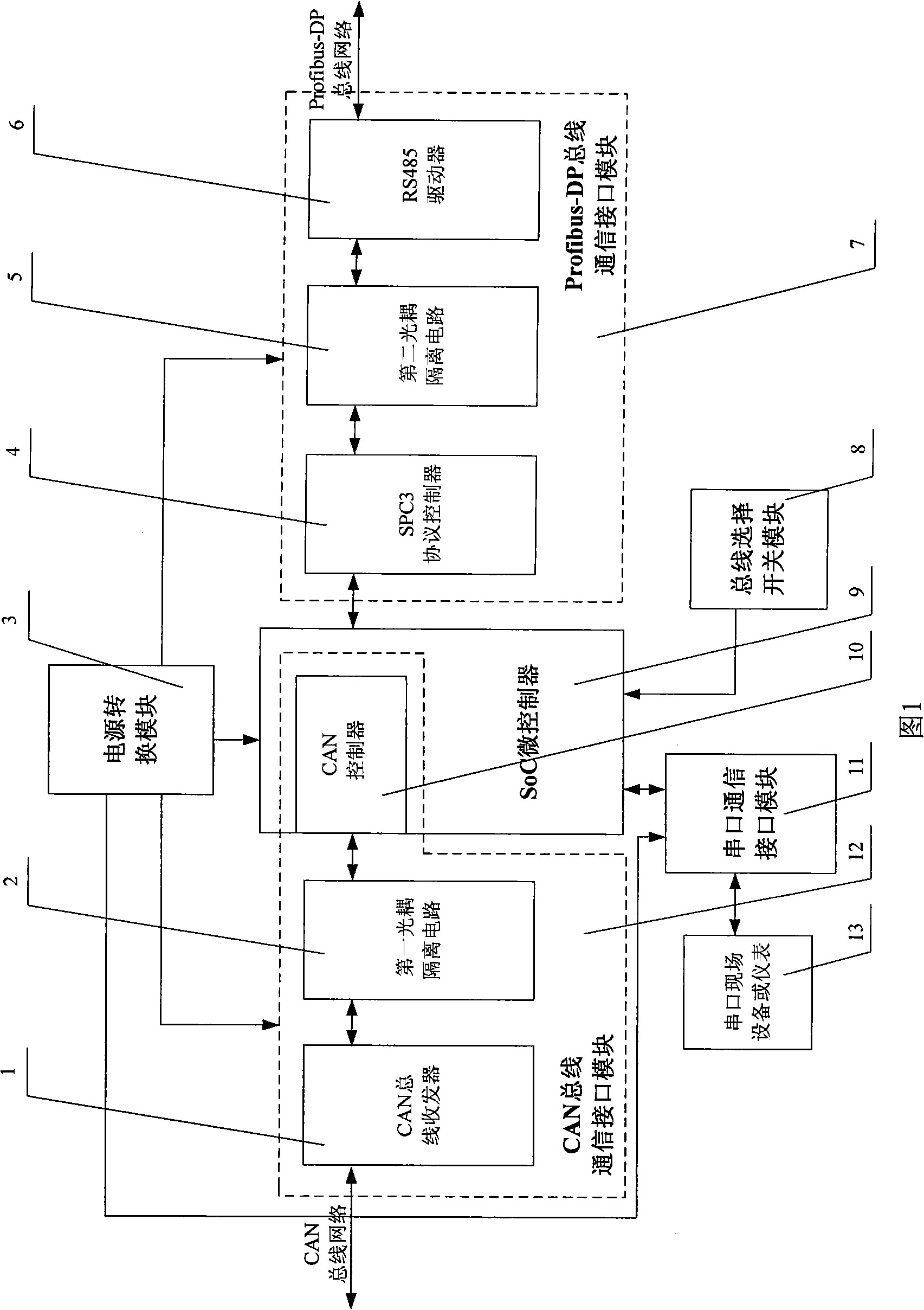
[0057] A dual-field bus interface converter is shown in Figure 1: the converter includes a SoC microcontroller 9, a CAN bus communication interface module 12, a Profibus-DP bus communication interface module 7, a serial communication interface module 11, and a power conversion module 3 And bus selection switch module 8.
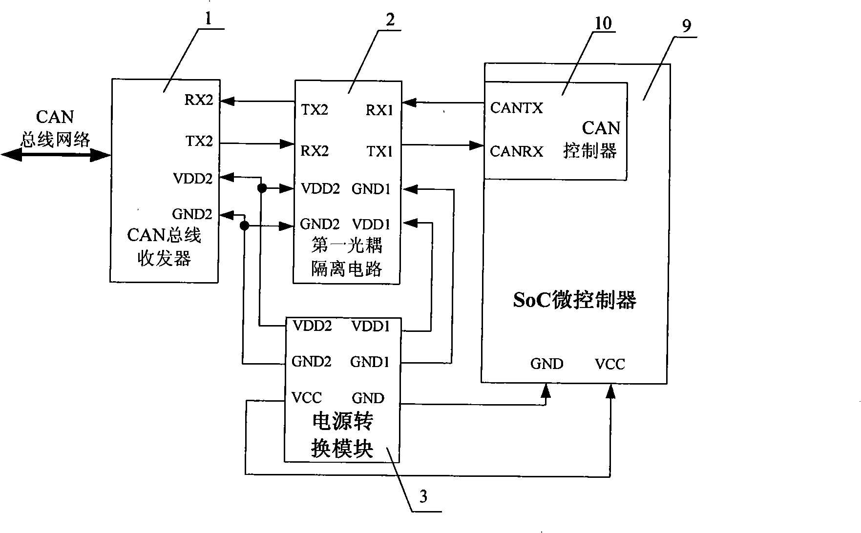
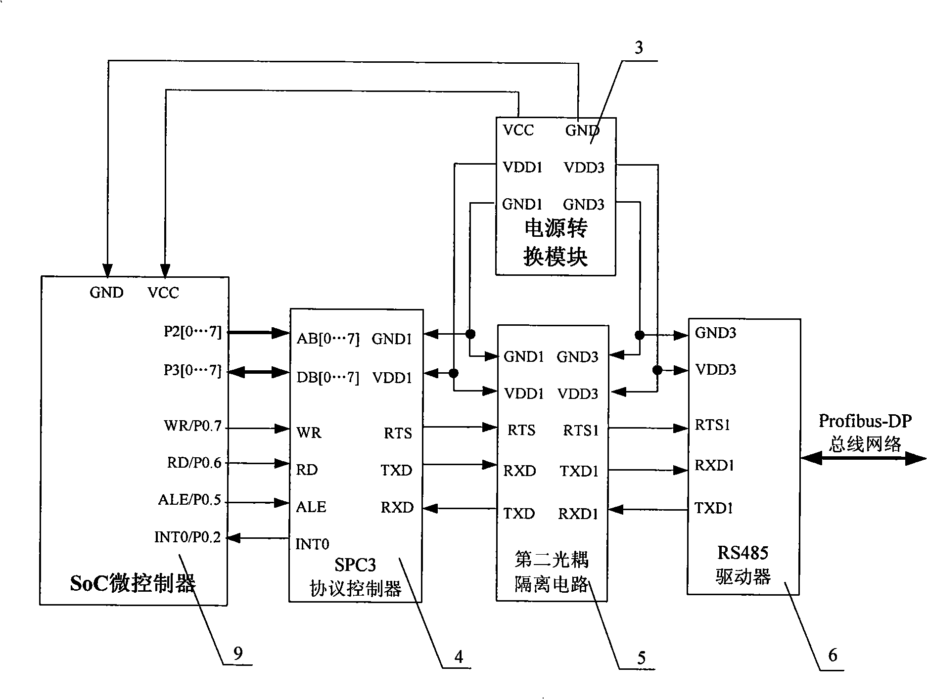
[0058] Wherein: the CAN bus communication interface module 12 is made up of the CAN controller 10 embedded in the SoC microcontroller 9, the first optocoupler isolation circuit 2 and the CAN bus transceiver 1; the Profibus-DP bus communication interface module 7 is composed of the SPC3 protocol controller 4. The second optocoupler isolation circuit 5 and the RS485 driver 6 are composed.
[0059] Present embodiment is shown in Fig. 1 for example, and one end...
PUM
 Abstract
Description
Claims
Application Information