Mobile recoverable oil sludge oil sand processing unit

A treatment device and oil recovery technology, applied in the direction of grease/oily substance/suspton removal device, dehydration/drying/concentrated sludge treatment, separation method, etc. Waste of precious energy and other issues, to achieve the effect of reducing total investment and operating costs, small footprint, and reliable performance

Inactive Publication Date: 2009-01-21
江苏冠豪环保科技有限公司
View PDF0 Cites 6 Cited by
  • Summary
  • Abstract
  • Description
  • Claims
  • Application Information

AI Technical Summary

Problems solved by technology

The direct landfilling of oil sludge and oil sand is the main oil sludge and oil sand disposal method adopted by most domestic oil fields, but this method not only wastes precious energy, but also may cause environmental pollution
Among them, the landfill method after solidification can reduce environmental hazards, but most of them cannot meet the current environmental protection requirements
[0005] ②Physical and chemical treatment: Various physical and chemical treatment methods are mostly aimed at recovering crude oil, so they are mainly suitable for oily sludge and oil sands with high oil content. The treatment process usually requires the addition of chemicals and special treatment facilities. The treatment process is complex and costly. higher
However, the land cultivation method and the composting method require a large area of ​​land, and the bioreactor method still has waste residues discharged, and the processing time is long and the operation is complicated
[0007] ④ Incineration method: Incineration must be carried out in a specially established incinerator, which can completely eliminate harmful organic substances in oil sludge and oil sands. If the comprehensive utilization of combustion heat energy is not considered, energy will be wasted
[0008] ⑤Use as fuel: as fuel is a comprehensive utilization of energy contained in oil sludge and oil sands, but the crude oil cannot be extracted

Method used


Image

  • Mobile recoverable oil sludge oil sand processing unit
  • Mobile recoverable oil sludge oil sand processing unit
  • Mobile recoverable oil sludge oil sand processing unit

Examples


Embodiment Construction

[0031] The present invention will be further explained below in conjunction with the accompanying drawings.

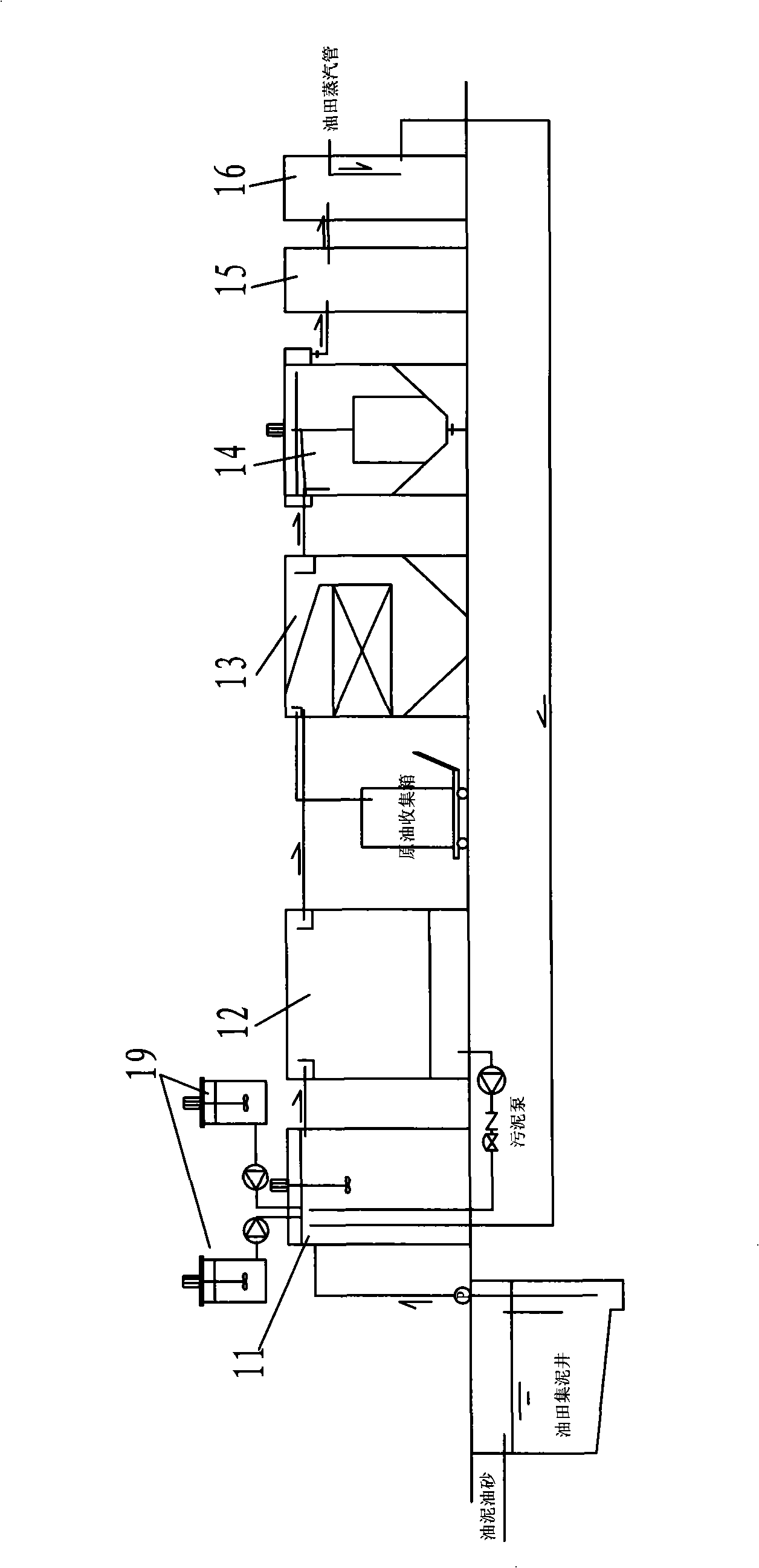
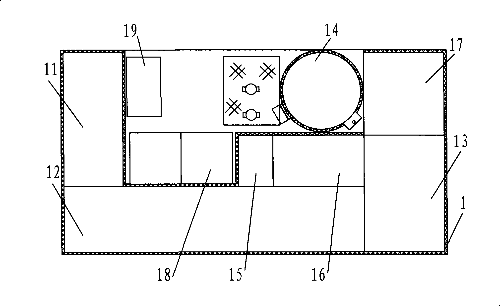
[0032] Such as image 3 , 4 As shown, the mobile recyclable oil sludge and oil sand treatment device of the present invention includes a first box body 1 and a second box body 2, and the first box body 1 and the second box body 2 are all provided with lifting rings for loading. The bottom of each box is welded by channel steel and steel plate.

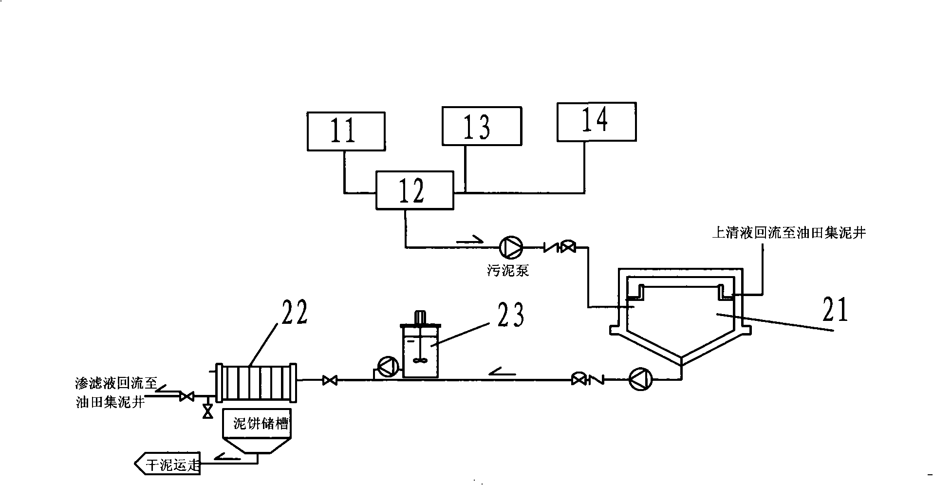
[0033]The first box body 1 is provided with a reaction tank 11 , a settling tank 12 , a grease trap 13 , an air flotation device 14 , a reclaimed water tank 15 , a hot water tank 16 , a replenishing water tank 17 , a dosing device 18 and a PLC control device 19 . The oil sludge and oil sand in the mud collection well are transported into the reaction tank 11 through a sludge pump installed in the first box 1, and a tank wall of the reaction tank 11 with a stirring device inside is shared with a section of the tank wall of the...


PUM


Abstract

The invention discloses a mobile treatment device for recoverable oil sludge and oil sand. The mobile treatment device comprises a first box body and a second box body, wherein both box bodies are provided with hoist rings, and bottoms of both box bodies are welded by channel steel and steel plates; the first box body is provided with a reaction tank, a settling tank, a separation tank, an airfloated device, a reclaimed water tank, a hot water tank, a water-replenishing tank, a dosing device and a PLC controlling device; and the second box body is provided with a sludge concentrated tank, a sludge pressure filter and a dosing device. The mobile treatment device has the advantages that the treatment device has a whole set of supply, and can be put on a trailer so as to be transported to and used at another oil field, thereby saving investment and ensuring convenient management; the treatment device greatly improves the treatment and recovery of oil sludge and oil sand in an oil field, and provides a complete set of device for separating and reclaiming oil, water, sludge and sand; meanwhile, the treatment device reduces environmental pollution without generating secondary pollution, and also increases the utilization rate of land and crude oil; moreover, the treatment device has the advantages of reliable equipment performance, stable operation, low cost, convenient management and maintenance, compact structure, small land occupation, economical and reasonable layout and less investment.

Description

technical field [0001] The invention discloses a mobile recyclable oil sludge oil sand treatment device. Background technique [0002] With the rapid development of the economy, the demand and dependence on energy are getting stronger and stronger, especially oil. However, the more surface and quantity of oil extraction, the more various pollutions will be produced. How to solve the pollution and water saving of oil fields has become a problem that oil fields are facing and must solve, especially oil sludge. The disposal of sand is the most urgent. In the process of oil field development, especially oil well production and downhole operation, some crude oil is inevitably released or carried to the land or well site by tubing, sucker rods, pumps and other downhole tools. These crude oil seeps into the ground soil and forms Oil sludge and oil sand; in addition, various oil tanks will also produce some oil sludge and oil sand during natural settlement. The composition of oil...

Claims


Application Information

Patent Timeline
Patent Type & Authority Applications(China)
IPC IPC(8): C02F11/12C02F1/40
Inventor 王顺才陈建蒋红军
Owner 江苏冠豪环保科技有限公司
Why Eureka
Try Eureka