
Vacuum system

A vacuum system and vacuum technology, applied in the field of vacuum systems, can solve problems such as the inability to realize small-caliber non-gravity pressurized discharge, unfavorable sewage system pipeline layout and construction, and unsatisfactory suction and discharge forces, etc., to achieve expanded sewage treatment range, improving system reliability, and smooth sewage discharge

Active Publication Date: 2009-01-21
湖南真创环保科技有限公司
View PDF1 Cites 17 Cited by
  • Summary
  • Abstract
  • Description
  • Claims
  • Application Information

AI Technical Summary

Problems solved by technology

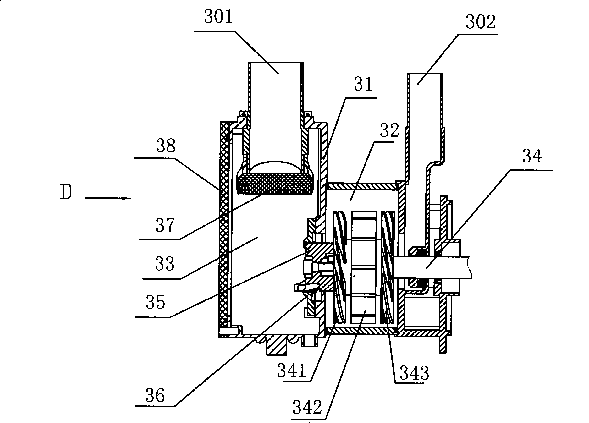
[0004] The invention also solves the technical problems that the rotary cam pump is prone to blockage, the pressurization capacity is not strong enough, the suction force and discharge force are not ideal enough, and the small-diameter non-gravity pressurized discharge cannot be realized, which is not conducive to the layout and construction of the sewage system pipeline. ;Provide a method that can grind and pulverize the dirt, effectively solve the problem of dirt clogging, expand the scope of sewage treatment, improve the suction force, discharge force and pressurization capacity, realize small-caliber non-gravity pressurized discharge, and facilitate the installation of sewage system pipelines A vacuum system for layout and construction

Method used


Image

  • Vacuum system
  • Vacuum system
  • Vacuum system

Examples


Embodiment 1

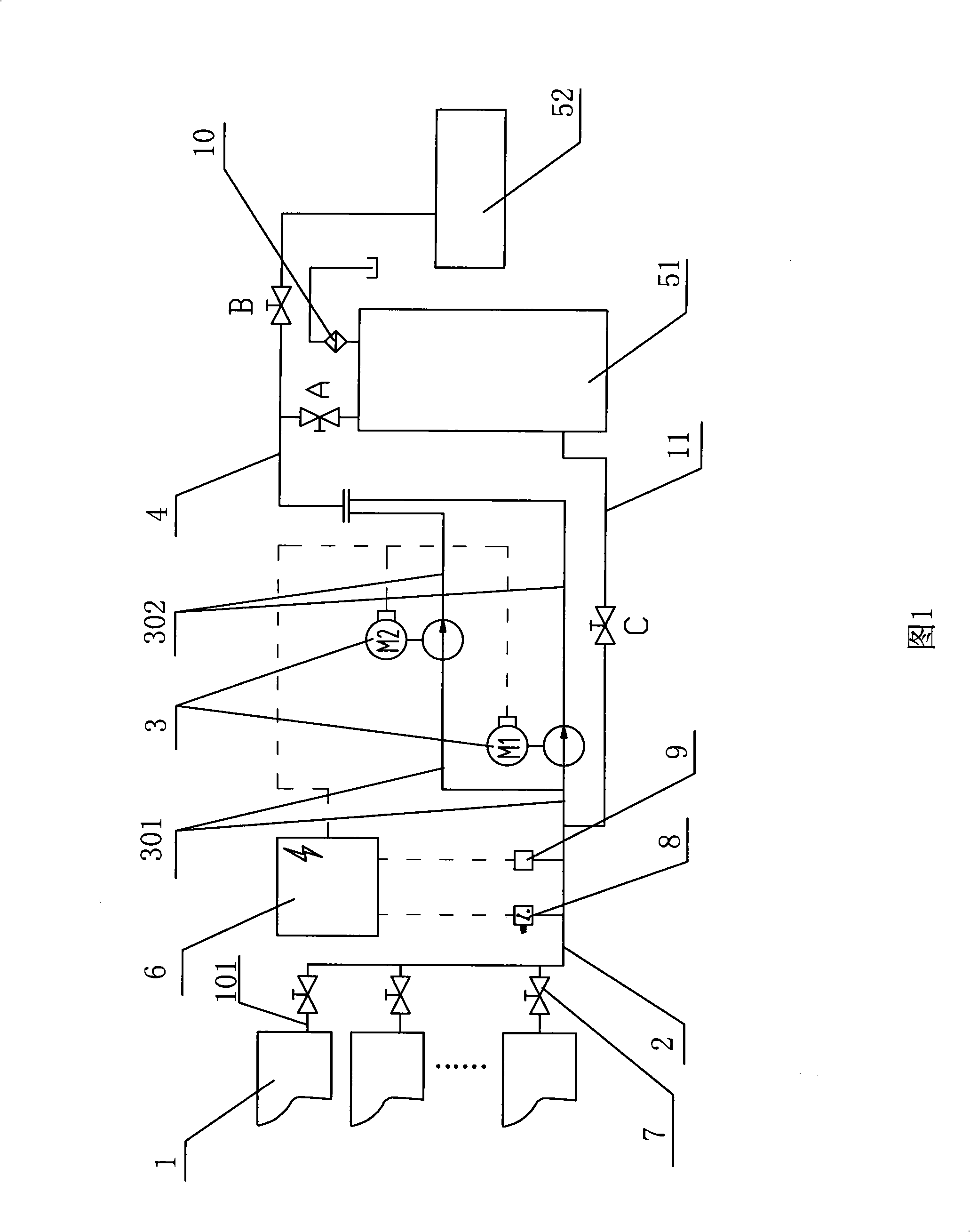
[0027]Embodiment 1: A vacuum system of this embodiment, as shown in FIG. 1 , includes multiple sewage sources 1 , two vacuum conveying pumps 3 , a waste collection place, and a control center 6 . The discharge pipe 101 of each sewage source 1 is connected to the sewage suction pipe 2 through the isolation ball valve 7, and the sewage suction pipe 2 is connected to the inlet pipe 301 of each vacuum conveying pump 3, and the outlet pipe 302 of each vacuum conveying pump 3 is connected to the sewage discharge Pipe 4, sewage pipe 4 is connected to the dirt collection place again. A vacuum pressure switch 8 and a pressure sensor 9 electrically connected to the control center 6 are installed on the sewage suction pipe 2 , and the vacuum delivery pump 3 is also electrically connected to the control center 6 . In the present embodiment, the dirt collection place includes dirt collection equipment 51 and sewage purification equipment or sewer 52, and a conversion ball valve A is instal...


PUM


Abstract

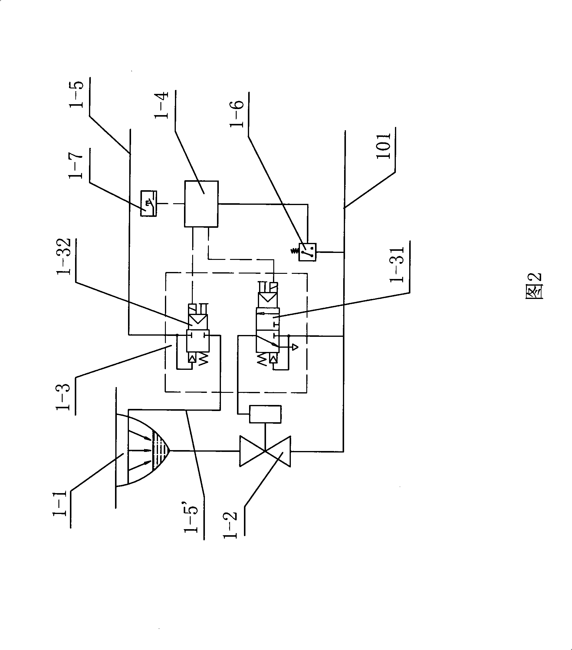
The invention relates to a vacuum system which comprises a plurality of drainage sources, a plurality of vacuum conveying pumps, a sewage collecting part and a control center. Each sewage source comprises a drainage pool with a sewage outfall, a vacuum release valve, a vapor integrated double electromagnetic valve and a control device; and the sewage outfall of the drainage pool is connected with a discharge pipe of the sewage source by the vacuum release valve. The discharge pipe of the sewage source is connected with a sewage suction pipe by an isolation ball valve; the sewage suction pipe is connected with an inlet pipe of each vacuum conveying pump; and an outlet pipe of each vacuum conveying pump is connected with a sewage discharge pipe which is connected to the sewage collecting part. A pressure detection device in electric connection with the control center is arranged on the sewage suction pipe; and the vacuum conveying pump and the control center are in electric connection. In the vacuum system, the control center carries out intelligent control that one or a plurality of the vacuum conveying pumps are opened according to the detected vacuum degree of the sewage suction pipe; the vacuum system can ensure the vacuum degree of the sewage suction pipe to make sewage discharging smooth, effectively saves energy, has simple control, reduces cost, improves the reliability of the system and is convenient to maintain.

Description

technical field [0001] The invention relates to a sewage or sewage discharge system, in particular to a vacuum system. Background technique [0002] Chinese patent document 01123161.0 discloses "a vacuum system", which relates to a method for transporting sewage using a vacuum system. device. For a reliable operating system, this method employs a rotary lobe pump to create a vacuum through which the sewage is transported to the sewage collection or discharge space. This kind of system requires a lot of electric valves to control. For each additional rotary lobe pump, at least two sets of electric valves must be added, and when the rotary lobe pump is used for sewage discharge, the rotary lobe pump must be changed while controlling the electric valve. The direction of rotation, as long as any valve fails, it will cause the sewage to overflow. On the other hand, rotary lobe pumps are prone to clogging when encountering larger, harder dirt or very soft paper or silk products...

Claims


Application Information

Patent Timeline
Patent Type & Authority Applications(China)
IPC IPC(8): E03F1/00F04C25/02F04C19/00F04C29/00
Inventor 赵海龙刘宇奇张磊
Owner 湖南真创环保科技有限公司
Learn More