
Lubricating system with trace amount

A micro-lubrication, threaded connection technology, applied in metal processing machinery parts, maintenance and safety accessories, metal processing equipment, etc., to achieve the effect of less consumables, low cost and convenient operation

Inactive Publication Date: 2009-01-28
BEIHANG UNIV
View PDF0 Cites 18 Cited by
  • Summary
  • Abstract
  • Description
  • Claims
  • Application Information

AI Technical Summary

Problems solved by technology

[0004] The purpose of the present invention is to propose a kind of micro-lubrication system applied in the field of mechanical processing to solve various problems of the existing liquid supply device. The sprayed coolant sprayed by the device can be directly used in mechanical processing processes such as metal cutting. It can be used as a lubricant liquid supply device in green cutting systems such as room temperature micro-lubrication, low-temperature spray cooling, and liquid nitrogen cooling. The device can adjust the amount of lubricant, and has the advantages of light weight, easy operation, less pollution, safe use and easy cleaning.

Method used


Image

  • Lubricating system with trace amount
  • Lubricating system with trace amount
  • Lubricating system with trace amount

Examples


Embodiment Construction

[0029] The working mode of the device of the present invention is introduced in detail below through a specific embodiment:

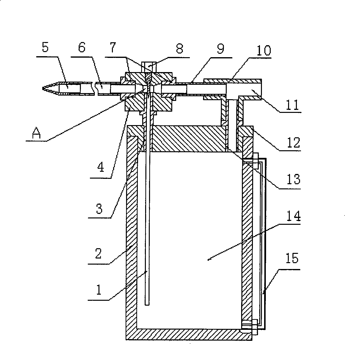
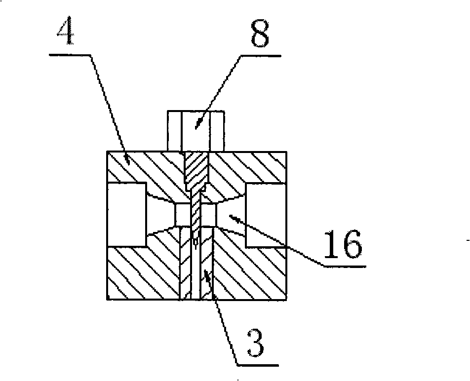
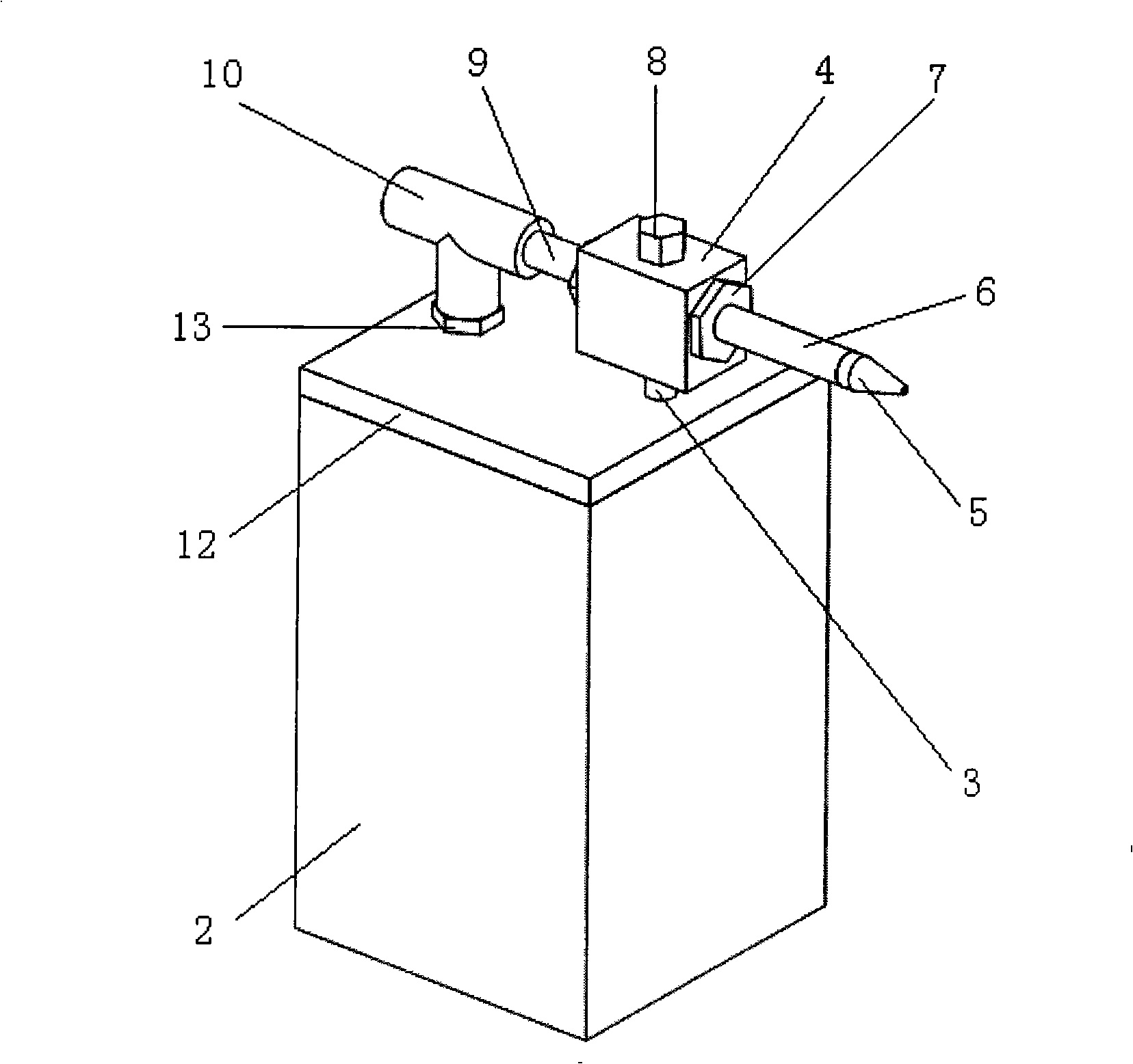
[0030] A kind of minimum quantity lubrication system of the present invention, such as figure 1 , image 3 As shown, the system consists of a cavity wall 2, an upper cover 12, a fluid guiding hose 1, a large threaded connecting column 13, a liquid suction device 4, a casing 9, a small threaded connecting column 3, a tee pipe 10, and a flow regulating valve 8 , transfer pipe 6 and nozzle 5.

[0031] The cavity wall 2 and the upper cover 12 form a hollow and closed cavity 14, and their junctions are provided with threaded holes, which are connected by screws.

[0032] The liquid guiding hose 1 passes through the central hole of the small thread connecting column 3 and is glued to the inner wall of the small thread connecting column 3 , and one end thereof is located at the circumferential wall in the through hole of the liquid suction device 4 . For in...


PUM


Abstract

A micro quantity lubrication system consists of a cavity wall, an upper cover, a liquid drainage flexible pipe, a large threaded joint pin, a liquid absorption device, a casing, a small threaded joint pin, a three-way pipe, a flow control valve, a transport pipe and a nozzle. In working process, compressed gas enters from a compressed gas inlet of the three-way pipe, flows through a 'contracting-expanding' hole in the liquid absorption device; the cross section of the hole becomes small, along which the gas pressure reduces; the intensity of the pressure in a cavity is the same as that of the compressed gas inlet, which leads the appearance of the pressure difference between the gas in the cavity and the gas in a straight-through hole, thereby leading the lubricant in the cavity to flow into the liquid absorption device, at the time the flow rate of the lubricant in the liquid drainage flexible pipe can be changed by changing the height of a flow control knob; simultaneously, pushed by the compressed gas, the lubricant in the liquid absorption device flows into the transport pipe and to the nozzle along the pipe wall, is atomized under the contraction effect of the nozzle and is sprayed out at a high speed along with the compressed gas. The device of the micro quantity lubrication system has the advantages of low material consumption, low cost and is suitable for mass production.

Description

(1) Technical field: [0001] The invention relates to a micro-quantity lubrication system, in particular to a micro-quantity lubrication device that delivers cutting lubricant to a nozzle for atomization and sprays it to a cutting area at a relatively high speed to lubricate and cool the cutting area. The utility model relates to a coolant supply device belonging to the field of mechanical processing. (two) background technology: [0002] In the process of mechanical processing, the disadvantages of traditional pouring cooling methods are becoming more and more obvious: from the perspective of environmental pollution and health, on the one hand, waste cutting fluid is an important source of pollution to soil and air; on the other hand, the chemical substances contained in cutting fluid will affect workers Cause harm and easily cause various diseases; from the perspective of use cost, on the one hand, the purchase, storage and post-processing of cutting fluid are expensive, on...

Claims


Application Information

Patent Timeline
IPC IPC(8): B23Q11/10
Inventor 袁松梅刘晓旭严鲁涛
Owner BEIHANG UNIV
Learn More