

Method for removing photoresist
A photoresist and cleaning solution technology, applied in photosensitive material processing, electrical components, semiconductor/solid-state device manufacturing, etc. Reduce the effect of dilution
- Summary
- Abstract
- Description
- Claims
- Application Information
AI Technical Summary
Problems solved by technology
Method used
Image

Examples
Embodiment Construction
[0037] The specific embodiments of the present invention will be described in detail below in conjunction with the accompanying drawings.
[0038] In the semiconductor integrated circuit process, the photoresist is spin-coated on the surface of the semiconductor substrate through the photolithography process to define the area to be etched or ion implanted; after the etching or ion implantation is completed, the photoresist on the surface of the semiconductor substrate needs be removed. The invention provides a method for removing a photoresist layer.
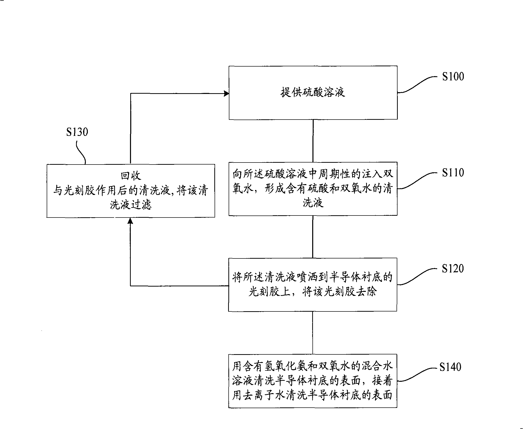
[0039] In the method for removing photoresist of the present invention, at first, provide sulfuric acid solution, this sulfuric acid solution is used as the cleaning solution of removing photoresist;
[0040] Next, periodically inject hydrogen peroxide into the sulfuric acid solution to form a cleaning solution containing sulfuric acid and hydrogen peroxide;
[0041] Periodically inject hydrogen peroxide into the cleaning sol...
PUM
 Abstract
Description
Claims
Application Information