Method for pressed forming multilayer electrical brush

A technology of pressing and forming brushes, which is applied in the field of pressing and forming multi-layer brushes, can solve the problems of no further disclosure and the inability to realize the continuous addition of different types of materials, and achieve the effect of multiple feeds

Inactive Publication Date: 2009-01-28
神奇电碳集团有限公司
View PDF2 Cites 7 Cited by
  • Summary
  • Abstract
  • Description
  • Claims
  • Application Information

AI Technical Summary

Problems solved by technology

However, the method and specific steps for loading each material into the mold are not further disclosed in the description, and the method of the prior art cannot realize the continuous addition of different types of materials.

Method used


Image

  • Method for pressed forming multilayer electrical brush
  • Method for pressed forming multilayer electrical brush
  • Method for pressed forming multilayer electrical brush

Examples


Embodiment 1

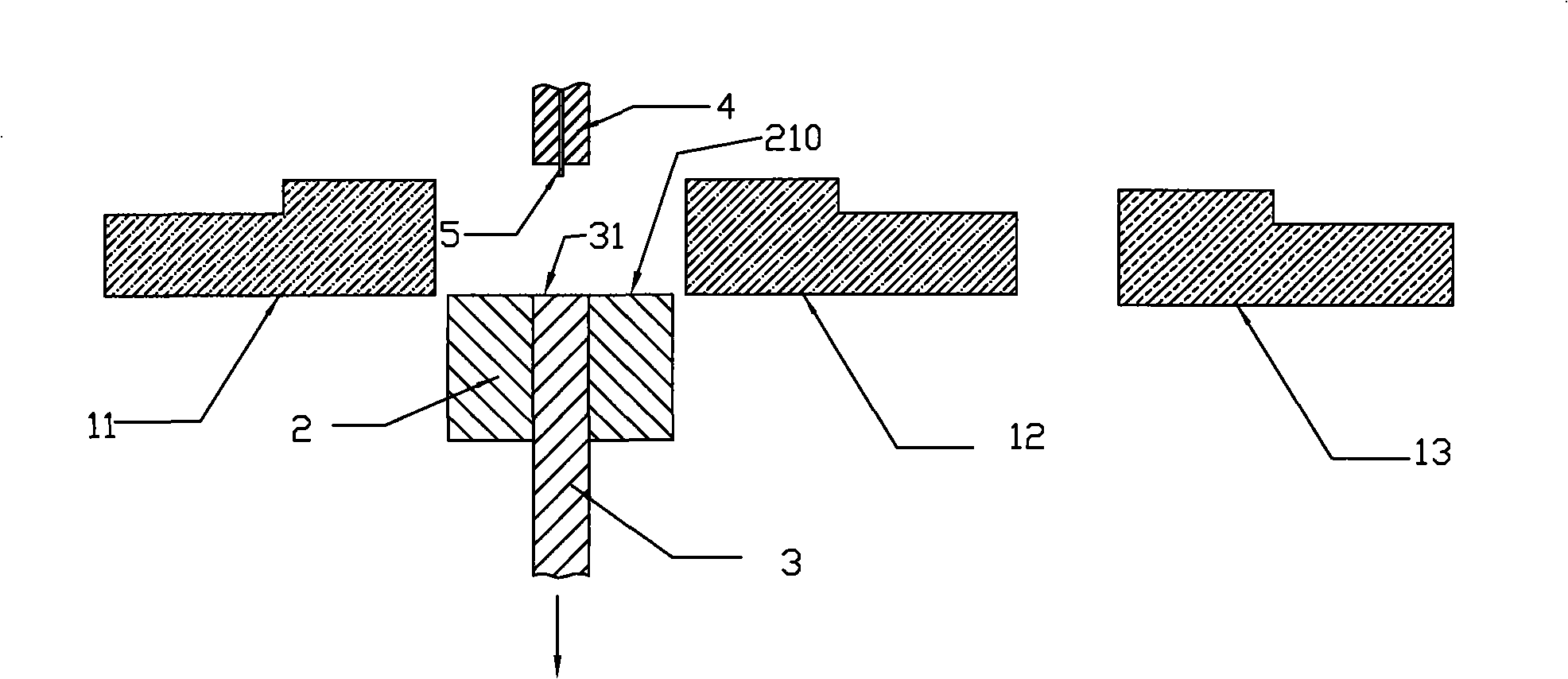
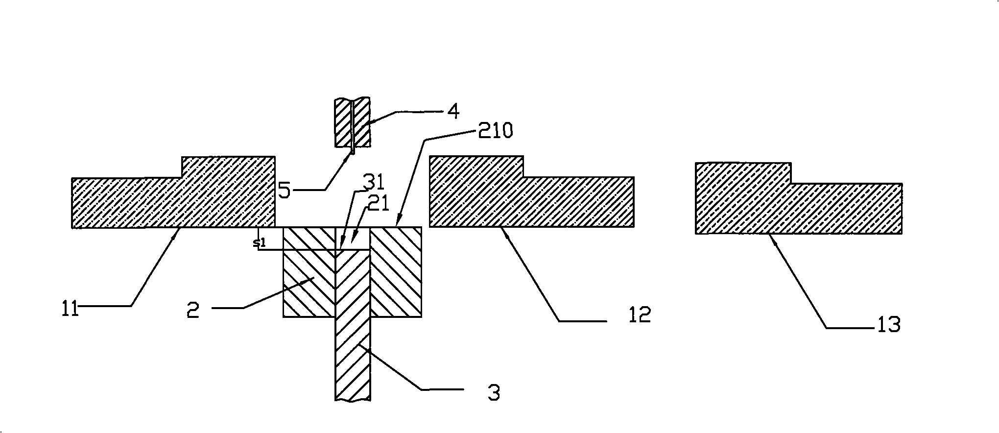
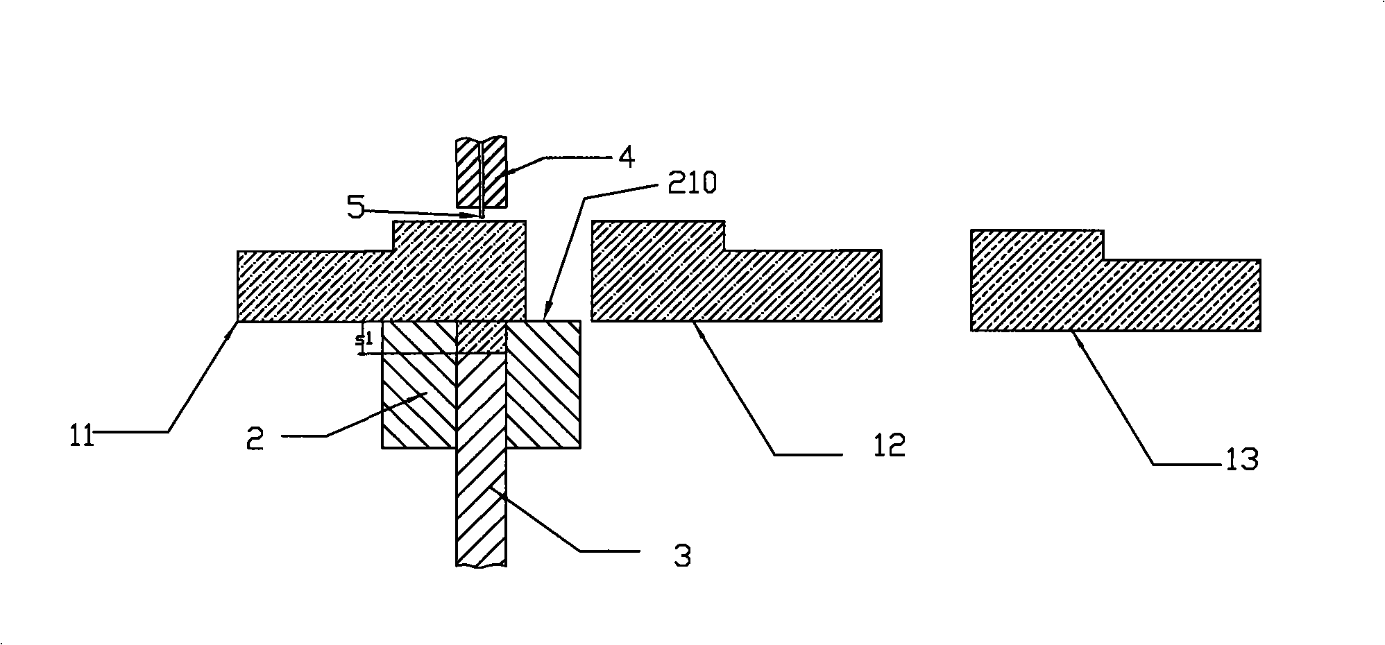
[0033] Such as Figure 1-Figure 8 As shown, this embodiment takes the manufacture of a three-layer brush as an example to illustrate the press-forming method of the multi-layer brush of the present invention. Such as figure 1 As shown, the first pusher 11, the second pusher 12, the third pusher 13, the die 2, the lower punch 3 located in the cavity 21 of the die 2 and the die located in the die 2. The upper punch 4 with a wire hole above and the wire 5 passing through the wire hole are all in the initial state, wherein the upper end surface 31 of the lower punch 3 is on the same plane as the cavity entrance of the die 2. 210 are on the same plane. Such as figure 2 As shown, the distance s1 that the upper end surface 31 of the lower punch 3 needs to move downward relative to the plane 210 where the cavity entrance is located is calculated according to the mass of the first raw material that needs to be filled, that is, the distance s1 for filling the first raw material The...

Embodiment 2

[0036] Such as Figure 9-Figure 12 As shown, this embodiment takes the manufacture of a two-layer brush as an example to illustrate the press-forming method of the multi-layer brush of the present invention. Such as Figure 9 As shown, each device is in the initial state, and the pusher 1 in the present embodiment has a first material storage device 61 and a second material storage device 62, and the first material storage device 61 and the second material storage device 62 are respectively loaded For different raw materials, the upper end surface 31 of the lower punch 3 is in the same plane as the plane 210 where the cavity entrance of the die 2 is located. Such as Figure 10 As shown, first calculate the distance s1 that the lower punch 3 moves downward relative to the plane 210 where the cavity entrance is located according to the quality of the first raw material that needs to be filled, that is, the quality of the first raw material is determined by the The upper end s...

Embodiment 3

[0039] Such as Figure 13-Figure 17 As shown, this embodiment takes the manufacture of a three-layer brush as an example to illustrate the press-forming method of the multi-layer brush of the present invention. Such as Figure 13 As shown, each device is in an initial state, and there are two pushers 1, and the first pusher 11 has a first storage device 61 and a second storage device 62, and the first storage device 61 and the second storage device The feeding device 62 is respectively loaded with different raw materials, the second pusher 12 is loaded with a kind of raw material, and the upper end surface 31 of the lower punch 3 is in the same plane as the plane 210 where the cavity entrance of the die 2 is located. Such as Figure 14 As shown, first, the distance s1 that the lower punch 3 needs to move downward relative to the plane 210 where the cavity entrance is located is calculated according to the mass of the first raw material that needs to be filled, that is, the m...


PUM


Abstract

The invention provides a press-molding method for multilayer electric brushes. The method is characterized by comprising the following: (1) a step of packing materials, i.e. a material pushing machine is used for orderly pushing raw materials needed for forming every layer of an electric brush into a die cavity of a female die; the material pushing machine clings to a plane where an inlet of the die cavity is to move, so as to ensure that every raw material after packing is level with the plane where the inlet of the die cavity is; a lower punch capable of moving up and down relative to the die cavity is arranged in the die cavity; the quality of every raw material pushed into the die cavity by the material pushing machine is controlled through the distance that the upper end face of the lower punch moves relative to the plane where the inlet of the die cavity is; and (2) a step of pressing, i.e. an upper punch arranged above the female die moves downwards so as to press-mold the raw materials in the die cavity. The press-molding method for multilayer electric brushes can realize continuous, precise and repeated feed.

Description

technical field [0001] The invention relates to a manufacturing method of a multilayer electric brush. Specifically, it is a press forming method of a multi-layer electric brush. Background technique [0002] The traditional brush molding machine adopts artificial feeding and powder filling, which is inconvenient to operate, labor-intensive and low in production efficiency, and cannot meet the needs of mass production of brushes. Chinese patent document CN2797021Y discloses a feeding device for a fully automatic hydraulic press formed by brush horizontal molding, which adopts a mechanical automatic feeding device and improves production efficiency. However, the above-mentioned press machine is not suitable for the manufacture of multi-layer brushes, because the composition of the raw materials required for each layer of the multi-layer brush is different. In the manufacturing process of the multi-layer brush, the brush body of the brush is pressed Different types and diffe...

Claims


Application Information

Patent Timeline
Patent Type & Authority Applications(China)
IPC IPC(8): H01R43/12
Inventor 虞海泽
Owner 神奇电碳集团有限公司
Why Eureka
Try Eureka