Grating anchor rod force-measuring device and method for monitoring anchor rod stress variation

A fiber grating and force-measuring device technology, which is applied in the direction of measuring the force of the change in optical properties of the material when it is stressed, can solve the high requirements of sensors such as waterproof, moisture-proof, crack-proof, and anti-corrosion, and it is difficult to realize automatic data. Acquisition and processing, affecting the reliability and service life of the instrument and other issues, to achieve the effect of easy protection and maintenance, light weight and simple structure

Inactive Publication Date: 2009-02-04
XIAN UNIV OF SCI & TECH
View PDF0 Cites 30 Cited by
  • Summary
  • Abstract
  • Description
  • Claims
  • Application Information

AI Technical Summary

Problems solved by technology

However, the above method cannot meet the requirements of long-term monitoring of anchor bolts. There are two reasons for this: on the one hand, the working environment of anchor bolts is harsh, and the requirements for sensors such as waterproof, moisture-proof, crack-proof, and anti-corrosion are high. It brings difficulties and directly affects the reliability and service life of the instrument; on the other hand, in the long-distance transmission of monitoring signals, it is difficult to realize automatic data collection and processing, and there are also complex structures, cumbersome installation processes, and one-time Use, difficult to protect and maintain, greatly affected by the environment

Method used


Image

  • Grating anchor rod force-measuring device and method for monitoring anchor rod stress variation
  • Grating anchor rod force-measuring device and method for monitoring anchor rod stress variation
  • Grating anchor rod force-measuring device and method for monitoring anchor rod stress variation

Examples


Embodiment Construction

[0024] Accompanying drawing is embodiment of the present invention.

[0025] Below in conjunction with accompanying drawing, content of the invention will be further described:

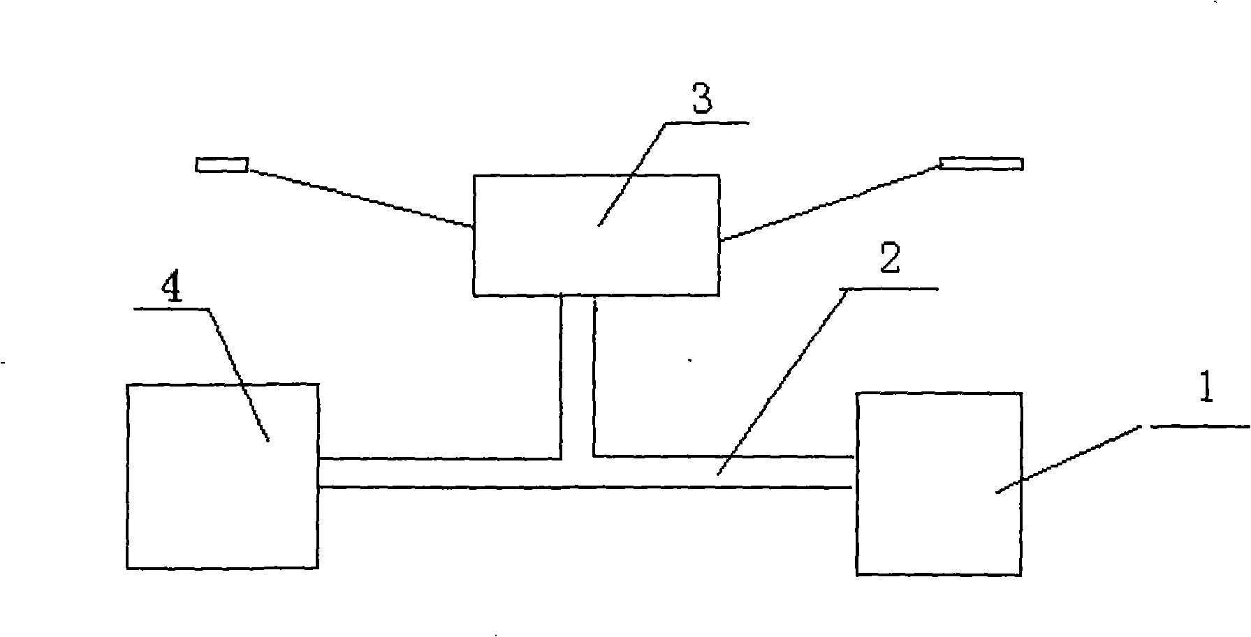
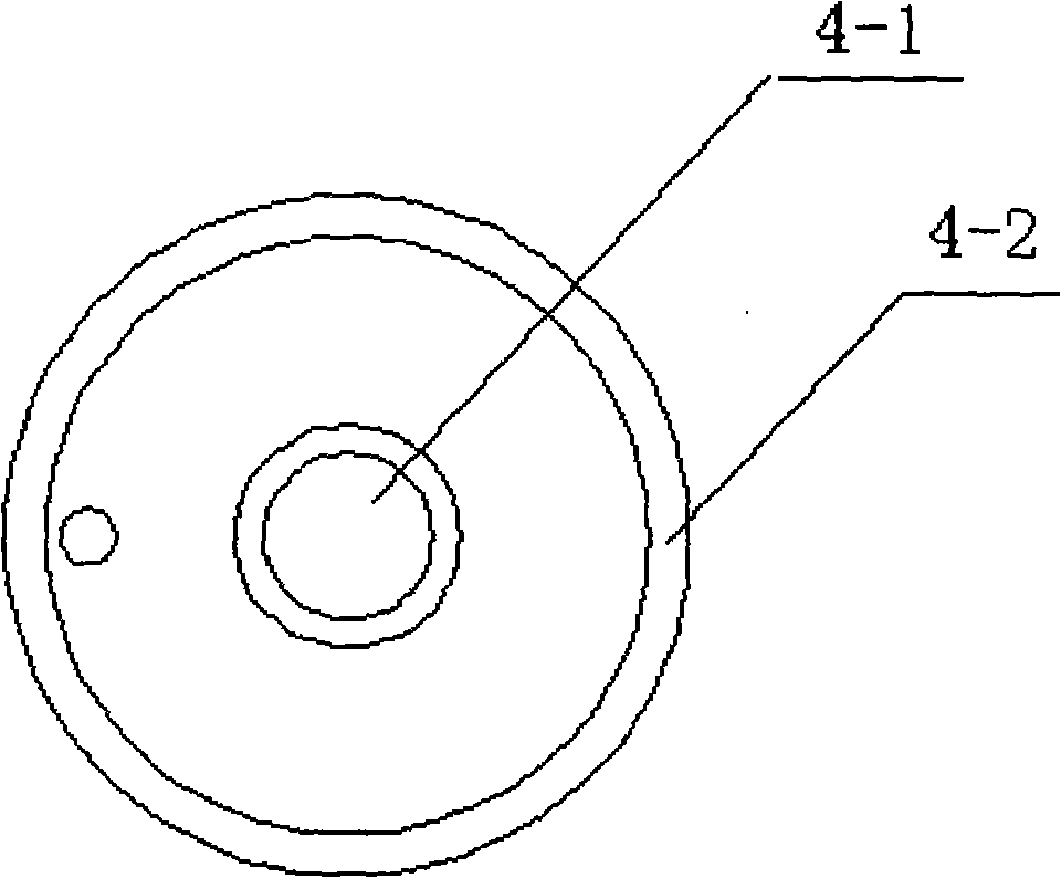
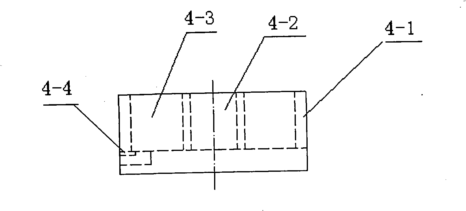
[0026] refer to figure 1 As shown, a fiber grating bolt force measuring device includes a pressure gauge 1, the pressure gauge 1 is connected to the T-shaped oil pipe 2, the horizontal pipe of the T-shaped oil pipe 2 is connected to the hydraulic cylinder 4, and the anchor rod is inserted into the hydraulic cylinder 4. In the inner hole, the vertical tube of the T-shaped oil pipe 2 is connected to the fiber grating sensor 3. The fiber grating sensor 3 includes a shell 5 connected with a cladding 6, and a fiber core 7 is placed in the cladding 6 inner cavity. The fiber core 7 is connected with at least two gratings 8 at intervals, and both ends of the fiber core 7 are connected to a fiber grating sensor network analyzer, and the fiber grating sensor network analyzer is connected to a computer.

[002...


PUM

PropertyMeasurementUnit
lengthaaaaaaaaaa

Abstract

The invention discloses an optical fiber raster anchor rod dynamometry device and an application method thereof, wherein, a manometer is connected with an oil pipe; a horizontal pipe is connected with a hydraulic cylinder; an anchor rod is inserted in the inner hole of the hydraulic cylinder; an vertical pipe is connected with an optical fiber raster sensor; the inside of the shell of the optical fiber raster sensor is connected with a cladding and a fiber core which is connected with a raster; the two ends of the fiber core are connected with an optical fiber raster sensing network analyzer and a computer. In the dynamometry device and the application method, an optical fiber raster demodulator detects the variation of the wavelength and converts the variation of the wavelength into an electrical signal; the optical fiber raster sensing network analyzer calculates the stress and strain of a point to be tested and a distribution state in the whole point to be tested; an optical fiber raster wavelength demodulation analyzing soft reads a testing data; a unitary linear regression model is established for getting the stress and strain value of the point to be tested under the action of external force, the invention has a simple structure, low cost and good anti-interference performance. Multi-parameter sensing measurement has a measurement with high precision and stable performance, which can be largely applied to the field of mine, tunnel or side slope, etc., and the signal can be transmitted far.

Description

technical field [0001] The invention relates to a force measuring device and a method for monitoring the stress change of an anchor rod, in particular to a fiber grating anchor rod force measuring device and a method for monitoring the stress change of an anchor rod. Background technique [0002] Existing mines or tunnels or slopes use bolts to reinforce rock or soil layers. The bolt monitoring instruments used are divided into resistance strain type, steel string type, hydraulic pillow type and other forms according to the type of sensor. [1]. However, the above method cannot meet the requirements of long-term monitoring of anchor bolts. There are two reasons for this: on the one hand, the working environment of anchor bolts is harsh, and the requirements for sensors such as waterproof, moisture-proof, crack-proof, and anti-corrosion are high. It brings difficulties and directly affects the reliability and service life of the instrument; on the other hand, in the long-dist...

Claims


Application Information

Patent Timeline
Patent Type & Authority Applications(China)
IPC IPC(8): G01L1/24
Inventor 李毅柴敬邱标
Owner XIAN UNIV OF SCI & TECH
Why Eureka
Try Eureka