Wind generating set
A technology for wind power generators and generators, which is applied to wind power generator components, wind power motor combinations, wind power engines, etc. It can solve problems such as inconvenient maintenance, high processing costs, and low speed of generators, so as to avoid gear stress, The effect of compact structure and small volume
- Summary
- Abstract
- Description
- Claims
- Application Information
AI Technical Summary
Problems solved by technology
Method used
Image

Examples
Embodiment Construction
[0028] The content of the present invention will be described in detail below in conjunction with specific embodiments. The specific language or sequence in the specific embodiments is only for explanation and demonstration, and should not have any limiting effect on the protection scope of the present invention.
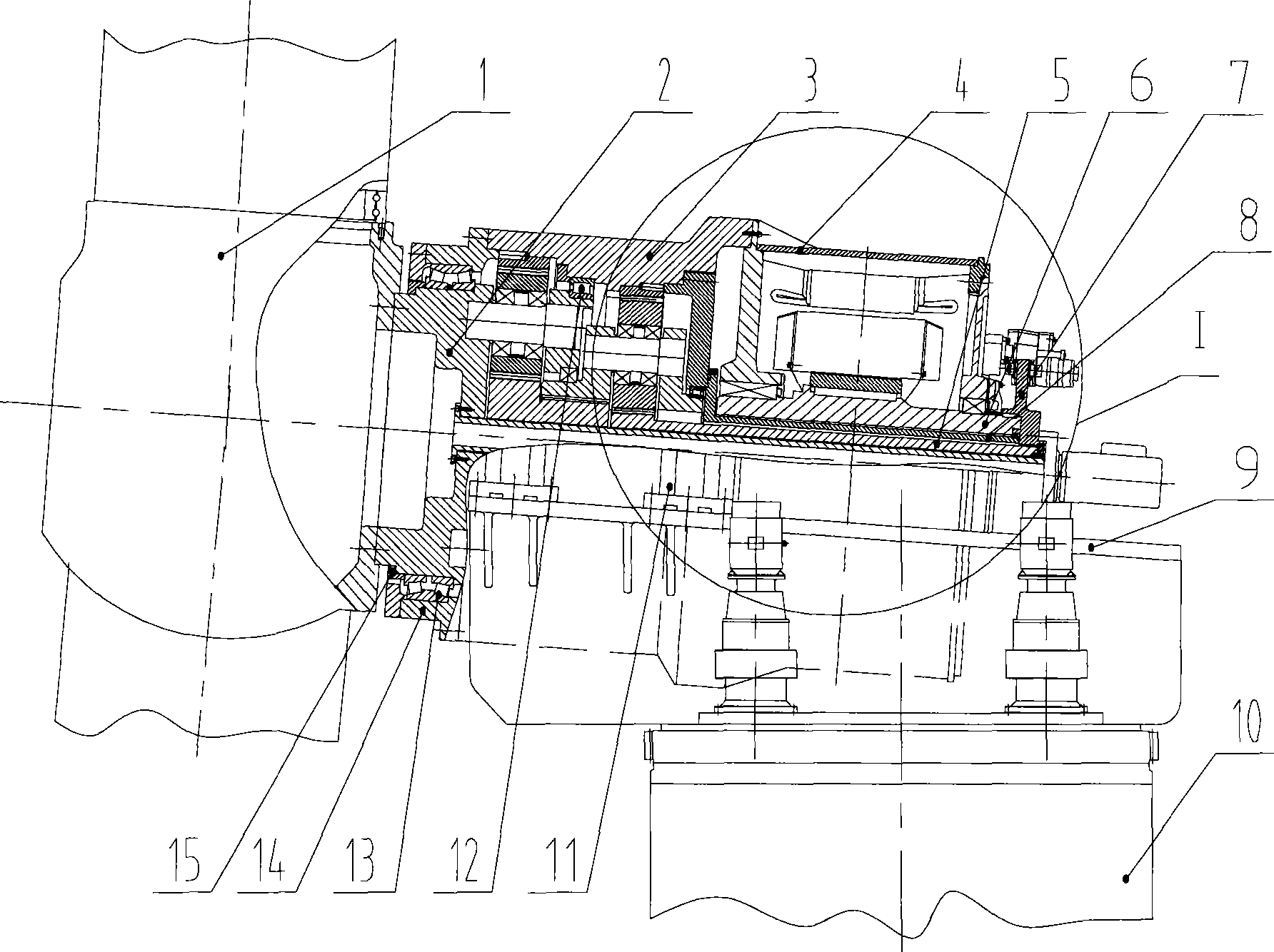
[0029] Please see figure 1 , figure 1 Front view of the generator set provided by the first embodiment of the present invention.
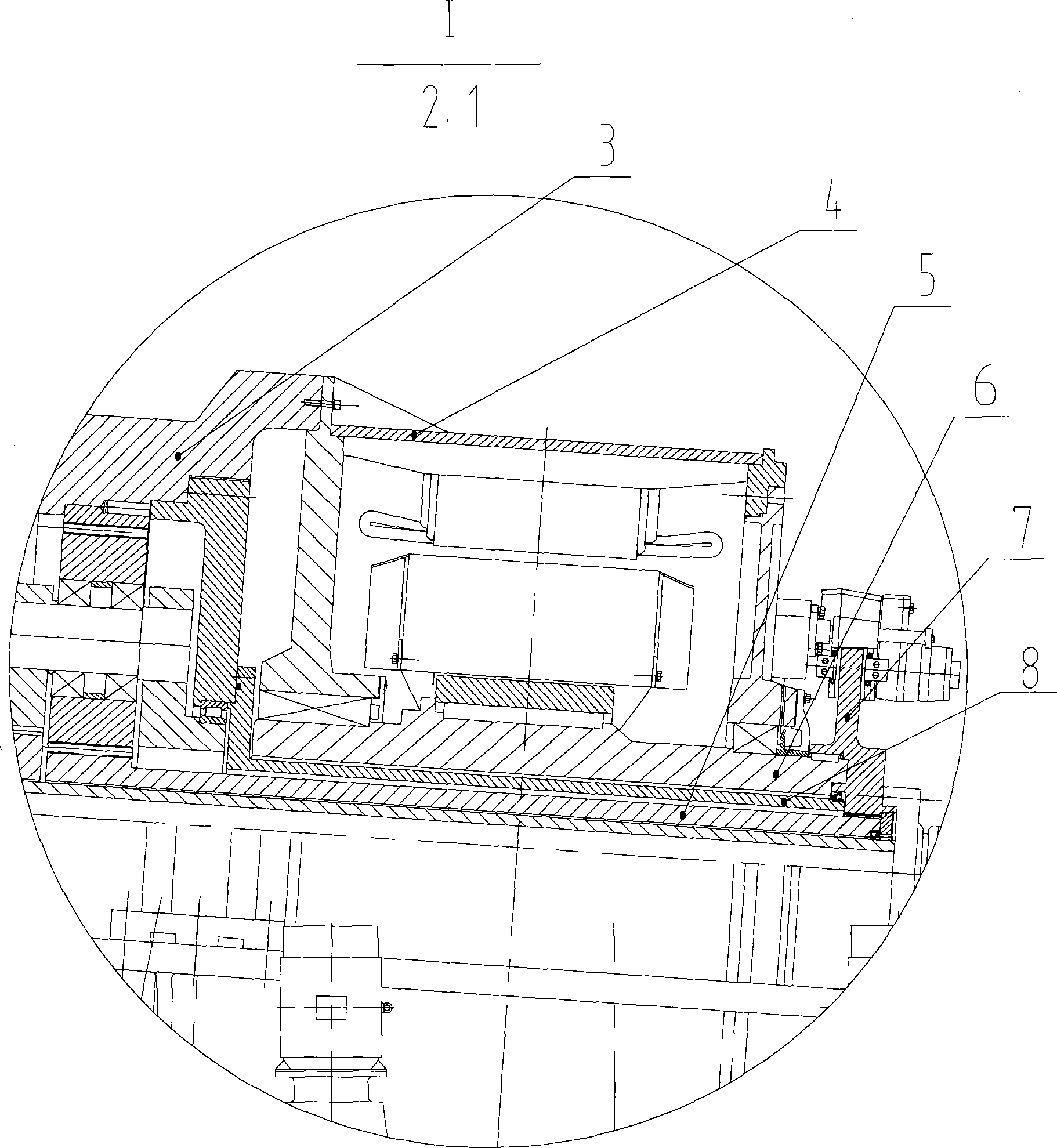
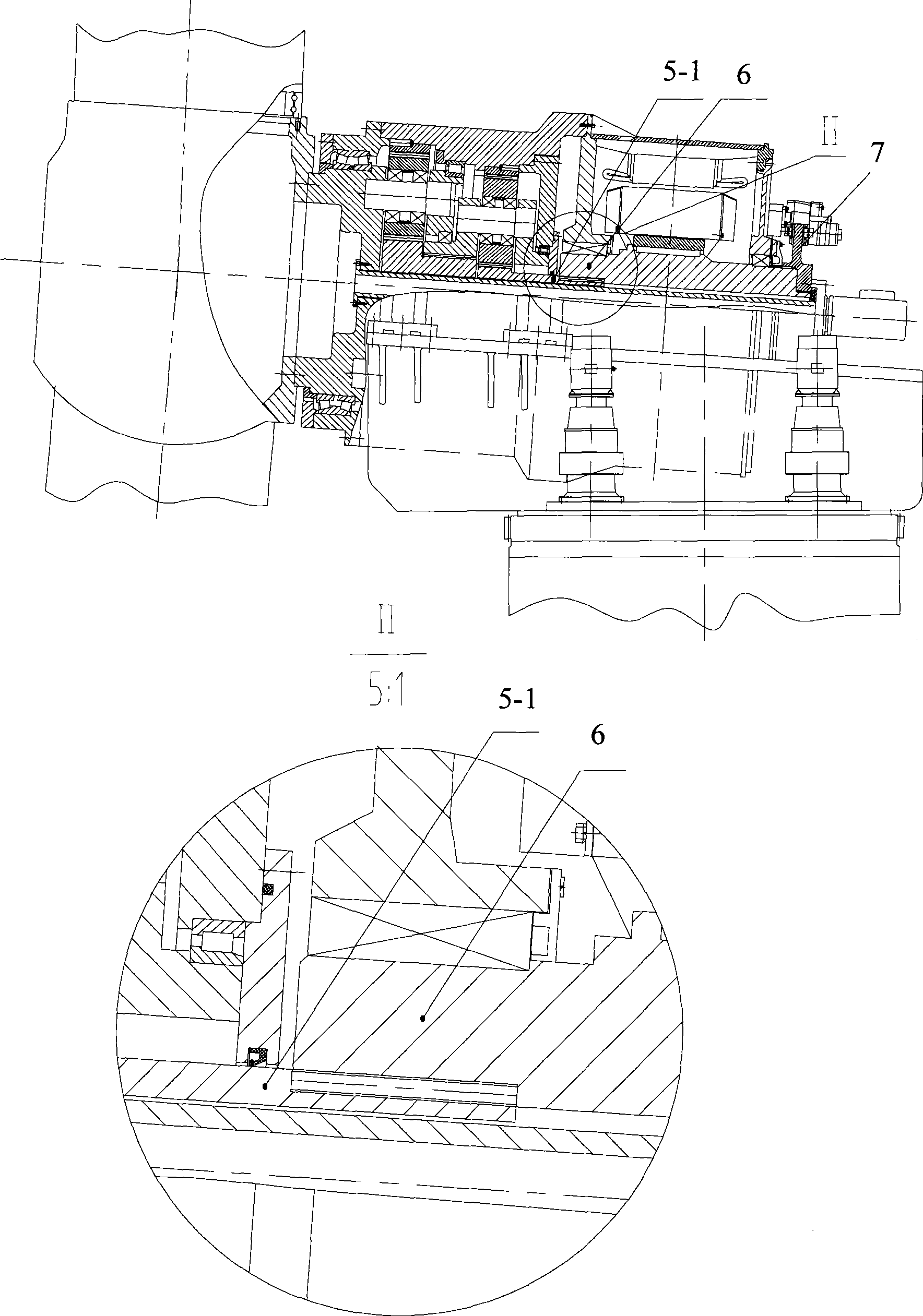
[0030] Such as figure 1 As shown, the generator set includes: wind wheel 1, planet carrier main shaft 2, gearbox 3, generator 4, gearbox output shaft 5, generator rotor shaft 6, main shaft brake disc 7, sealing sleeve 8, and nacelle underframe 9. Tower 10, gearbox support 11, auxiliary bearing 12, main bearing 13, ring 14, retaining ring 15, etc.
[0031] The wind wheel 1 includes blades and a hub. Gearbox 3 is a two-stage planetary gearbox with a speed-up ratio between 1:15 and 1:25. The gearbox adopts the first-stage planet carrier...
PUM
 Abstract
Description
Claims
Application Information