

Flat hot pipe for cooling electron device and processing technology thereof
A flat-plate heat pipe and electronic device technology, applied in metal processing equipment, manufacturing tools, indirect heat exchangers, etc., can solve the problems of high cost and complex system, reduce material consumption, large heat transport volume, and reduce material cost Effect
- Summary
- Abstract
- Description
- Claims
- Application Information
AI Technical Summary
Problems solved by technology
Method used
Image

Examples
Embodiment Construction
[0025] The present invention will be further described below in conjunction with the accompanying drawings.
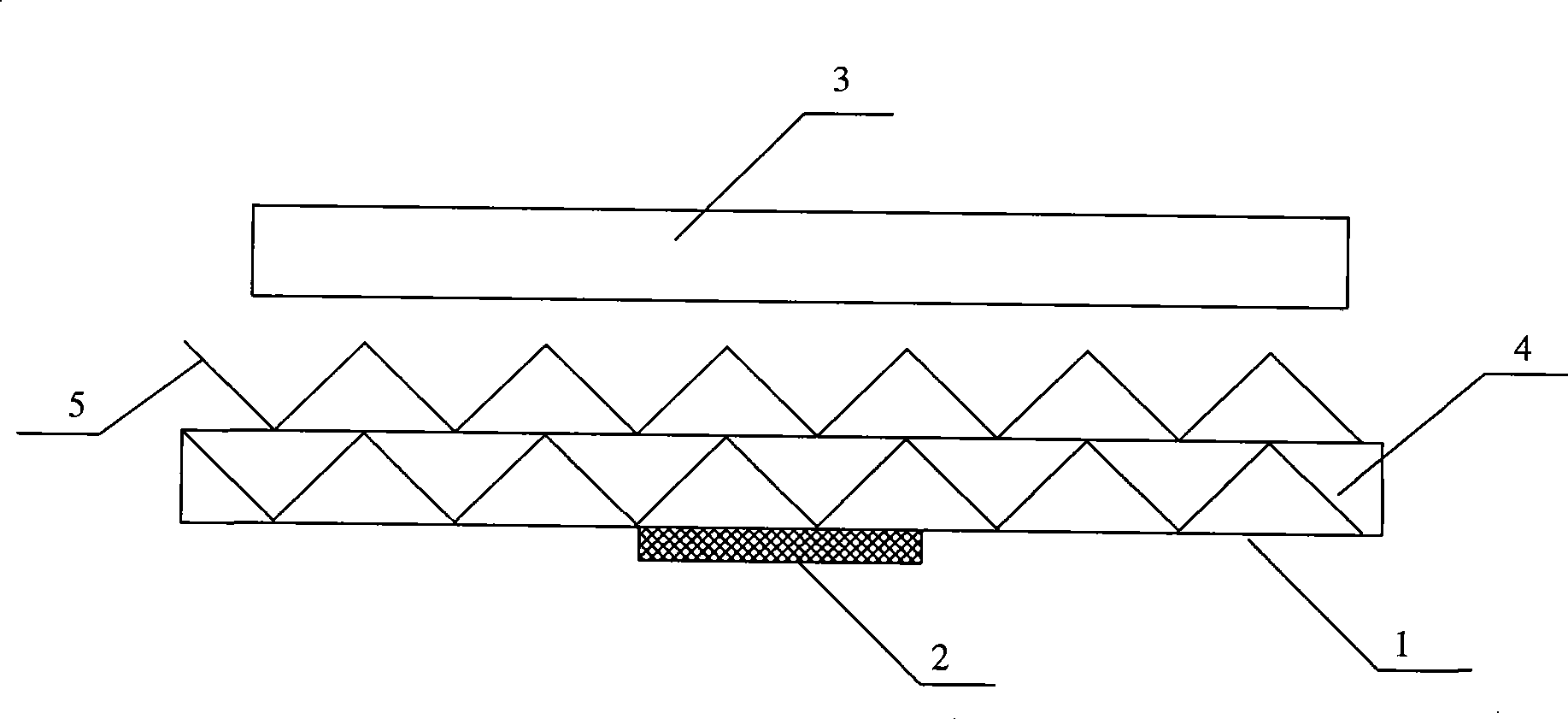
[0026] Such as figure 1 Shown is a schematic structural view of the flat heat pipe of the present invention.
[0027] The heat-absorbing section of the heat-absorbing plate 1 is closely bonded to the heating surface of the electronic components through heat-conducting silica gel. The fan 3 is arranged on the upper part of the outer fin 5 of the flat heat pipe. heat is lost to the atmosphere.
[0028] The inner fin 4 is arranged in the flat frame of the heat absorbing plate 1, and the inner fin 4 is located between the upper and lower end faces of the frame. The inner fin 4 shown in the figure is a plate with a W-shaped corrugated structure, and the inner fin 4 The peaks and valleys of the corrugated structure are respectively connected to the inner wall of the heat absorbing plate 1, and each adjacent peak and valley on the inner fin 4 forms a hole-shaped pipeline wi...
PUM
 Abstract
Description
Claims
Application Information