Miniature balanced antenna with differential feed

一种馈电、差分的技术,应用在天线、天线零部件、使天线同时工作在不同波段的装置等方向,能够解决平衡天线系统体积大、很难设计、平衡天线系统复杂阻抗匹配电路等问题,达到降低性能的效果

Inactive Publication Date: 2009-02-18
HONG KONG APPLIED SCI & TECH RES INST
View PDF0 Cites 4 Cited by
  • Summary
  • Abstract
  • Description
  • Claims
  • Application Information

AI Technical Summary

Problems solved by technology

[0004] In comparison, state-of-the-art balanced antenna systems tend to be bulky, and so are usually limited to applications where low loss is more important than space
Also, balanced antenna systems often employ complex impedance matching circuits that are expensive and / or difficult to design

Method used


Image

  • Miniature balanced antenna with differential feed
  • Miniature balanced antenna with differential feed
  • Miniature balanced antenna with differential feed

Examples


Embodiment Construction

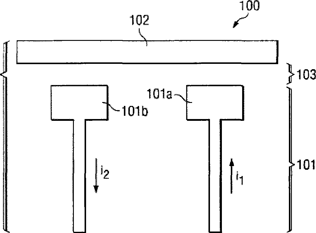
[0020] figure 1 A typical antenna system 100 for one embodiment of the invention is described. System 100 includes metal feed element 101 and metal parasitic element 102 . Individual feed elements 101a and 101b are "balanced" in that their currents (or potentials) are equal in magnitude and out of phase along their respective paths. Therefore, it is also a fact that the feeding element 101 is a differential structure with one side serving as the "+" side and the other side serving as the "" side. Gap 103 is a dielectric gap that may include air, plastic, fiberglass, or other dielectric material.

[0021] Metal element 102 is a parasitic element that is symmetrical with respect to the polarity of feed element 101 and separated by gap 103 . The parasitic element 102 has one or more resonance frequencies, and when an RF signal is supplied to the feeding element 101 at one resonance frequency, the parasitic element 102 resonates due to capacitive coupling. Feed element 101 als...


PUM


Abstract

An example antenna system includes a parasitic element and a symmetrical element fed by a balanced RF signal source. The fed element is operable to couple with the parasitic element, thereby causing the parasitic element to resonate at a first frequency band. Thus, the fed element is operable to act as a balanced capacitive feed for the parasitic element. Also, the parasitic element is symmetrical with respect to a polarity of the fed element.

Description

technical field [0001] The present invention relates generally to antenna systems, and more particularly to balanced antenna systems with differential feeding. The invention also relates to a satellite antenna system operating over a wide bandwidth. Background of the invention [0002] Prior art systems, both consumer and commercial, typically employ unbalanced antennas to transmit and receive radio frequency (RF) signals. Most unbalanced antennas have an asymmetric radiating section and are fed by an unbalanced transmission line (such as a coaxial cable or microstrip line) or source. An example of an unbalanced antenna is the common monopole antenna system, which has a single antenna element (a vertical straight metal rod with a length of 1 / 4 free-space wavelength, ), mirrored by a flat horizontal ground plane. There are several reasons why prior art systems employ unbalanced antennas. For example, most commercially available measurement equipment is designed to measur...

Claims


Application Information

Patent Timeline
Patent Type & Authority Applications(China)
IPC IPC(8): H01Q1/00
CPCH01Q1/36H01Q5/0062H01Q1/241H01Q19/005H01Q5/378
Inventor 柳江平麦志伦
Owner HONG KONG APPLIED SCI & TECH RES INST
Why Eureka
Try Eureka