Busbar connection device

A busbar connection and busbar connector technology, applied in the direction of connection, conductive connection, electrical component connection, etc., can solve the problems of easy loosening of insulating sleeves, large space occupation, exposed cable heads, etc., and achieves low technical level requirements and device structure. Small size, good insulation performance

Active Publication Date: 2009-02-25
SHANGHAI MUNICIPAL ELECTRIC POWER CO +1
View PDF0 Cites 9 Cited by
  • Summary
  • Abstract
  • Description
  • Claims
  • Application Information

AI Technical Summary

Problems solved by technology

[0003] The technical level of the construction personnel is uneven, and the cable connection has certain technical requirements. The steps of the connection operation are complicated, and the connection between the electrical equipment and the electrical equipment is often unreliable due to human factors, resulting in unnecessary quality when the equipment is running. ACCIDENT
[0004] When using cable connection, the bending radius of the cable installation and the working space of the construction personnel must be considered. This requires that there must be a considerable distance between the electrical equipment, resulting in the structure of the connected electrical equipment being not compact and occupying a large space. Limits the s

Method used


Image

  • Busbar connection device
  • Busbar connection device
  • Busbar connection device

Examples


Embodiment 1

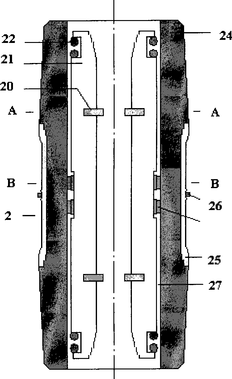
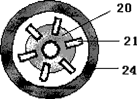
[0024] A bus connection device, characterized in that it is a supporting product composed of two bus insulators 1 and a bus connector 2, the structures of the two bus insulators 1 are exactly the same, and the bus insulator 1 includes an insulating cover 10 and an electrical contact 11, The material constituting the insulating cover 10 is epoxy resin, the insulating cover 10 is cup-shaped, q mounting holes 103 are evenly distributed on the cover opening 101 of the insulating cover 1, q is a natural number from 3 to 8, and each mounting hole 103 is sealed Intrinsic insert nut 104, the constituent material of electric contact 11 is copper, the bottom, middle part and head of electric contact 11 are respectively cylindrical, cylindrical and truncated cone, electric contact 11 is sealed in insulating cover 10 and insulated The central part of the cover bottom 102 of the cover 10, the bottom of the electric contact 11 runs through the cover bottom 102 of the insulating cover 10, the...

Embodiment 2

[0026] Except for the following differences, the remaining parts are identical to Example 1.

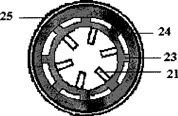
[0027]The busbar connector 2 also includes a shielding sheath 25, a grounding spring coil 26 and a grounding wire. The middle ring line of the insulating sheath 24 has a circular groove in cross section. The material constituting the shielding sheath 25 is silicon rubber. The shielding sheath The sleeve 25 is in the shape of a round tube, the grounding spring ring 26 is a thin spring connected end to end, the grounding wire is an insulated wire, the shielding sheath 25 is hooped in the middle of the outer wall of the insulating sheath 24, and the grounding spring coil 26 is hooped in the shielding sheath 25 in the depression, the wire at one end of the grounding wire is twisted with the grounding spring coil 26, and during use, the other end of the grounding wire is connected to the grounding wire terminal of a current-carrying busbar place equipment.

Embodiment 3

[0029] Except for the following differences, the remaining parts are identical to Example 1. m=12, n=4, p=8, q=6.


PUM


Abstract

The invention relates to a bus coupling device, which comprises two bus insulators and a bus connector. A plurality of contacts are buckled with gaps which are mutually corresponding on two lining rings to form a hollow column; a plurality of spring rings and two gear rings are respectively hooped in two spring gaps and gear ring gaps of the hollow column; the hollow column, the spring rings and the two gear rings form a conductive body which is fixed inside an insulating sheath through teeth of the gear rings and an inner wall of the insulating sheath. When in use, two current-carrying busesare respectively connected with electrical contacts of the two bus insulators; the two ends of the bus connector are respectively buckled with the electrical contacts of the two bus insulators; the two current-carrying buses are connected together through one bus insulator, the bus connector and the other bus insulator. The bus coupling device has the advantages of easy installation, cabinet structure and no exposed conductive part and can be used for the connection between two close high-voltage high-current electric apparatuses, the power transmission is not easy to be influenced by the outside, and the safety and the stability for the power transmission can be ensured.

Description

technical field [0001] The invention relates to a busbar connection device, more precisely, a high-voltage, high-current busbar connection device, which belongs to the technical field of power distribution. Background technique [0002] In the power distribution technology of urban and rural power grids, it is a routine job to connect the current-carrying busbar of one electrical device with the current-carrying busbar of another electrical device. The potential and carrying capacity of these current-carrying buses are in the order of 10kV-25kV and 200A-600A, respectively. Background Art The technical solution to this technical problem is: the current-carrying busbars of the two electrical equipment are led out from the respective electrical equipment through the conductors of the respective insulating porcelain bottles, and then the conductors of the two insulating porcelain bottles are connected together by cables. Although this cable connection method is technically very...

Claims


Application Information

Patent Timeline
IPC IPC(8): H02G15/00H01R4/48H01R11/00
Inventor 任苗佳唐继龙姜益民周洪滨华杰陆如
Owner SHANGHAI MUNICIPAL ELECTRIC POWER CO
Why Eureka
Try Eureka