

Internal combustion heating moving-bed type biomass pyrolysis liquefying apparatus
A biomass pyrolysis and liquefaction device technology, applied in the field of pyrolysis and liquefaction devices, can solve the problems of limited heat, unavoidable reactor and method shortcomings, and achieve the effects of improving utilization, reducing residence time, and reducing production costs
- Summary
- Abstract
- Description
- Claims
- Application Information
AI Technical Summary
Problems solved by technology
Method used
Image

Examples
Embodiment Construction
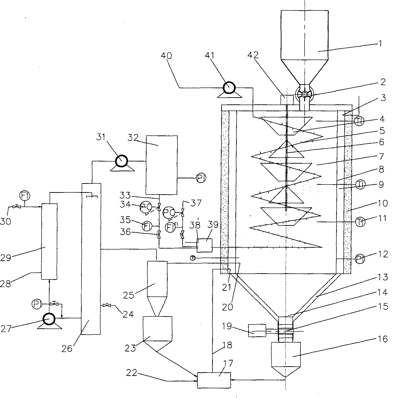
[0032] see figure 1 , the present embodiment adopts the cylindrical reactor 7, and in the inside of the cylindrical reactor 7, a serpentine internal combustion pipeline 5 is arranged, and the entrance of the serpentine internal combustion pipeline 5 is positioned at the bottom of the cylindrical reactor 7, and its outlet is from the cylinder. The top of the tubular reactor 7 extends to the outside of the reactor;
[0033] On the top of the cylindrical reactor 7, a blanking control valve 2 is set, and the feeding port is located at the top eccentric position of the cylindrical reactor 7, and on the central axis of the cylindrical reactor 7, a cone with a cone is set. The rotating shaft 6 of the funnel 4, and there is a conical distributing umbrella between the conical funnels 4, so that the biomass flowing out from the previous conical funnel 4 flows to the next conical funnel after being dispersed by the conical distributing umbrella 4, the residence time of biomass in the re...
PUM
 Abstract
Description
Claims
Application Information