
Rotary motor and method for manufacturing electric brush thereof

A technology of rotating motor and direction of rotation, which is applied in the manufacture of brushes, rotary current collectors, and contact parts, etc., can solve the problems of shortening operation processing time, long time, and inability to take into account the improvement of brush wear life, etc., so as to shorten the operation processing time. effect of time and longevity

Active Publication Date: 2009-03-04
MITSUBISHI ELECTRIC CORP
View PDF2 Cites 2 Cited by
  • Summary
  • Abstract
  • Description
  • Claims
  • Application Information

AI Technical Summary

Problems solved by technology

[0006] The conventional method is to provide a sliding surface at one end of the axial direction of the brush in order to reduce the noise of the sliding sound. However, the inclined surface provided in the axial direction of the brush is formed in a straight line with respect to the axial direction, so that the sliding The surface is gradually separated from the outer peripheral surface of the commutator in the axial direction, so in the case of a brush with a small inclination angle, in other words, when the inclined surface is close to parallel to the outer peripheral surface of the commutator, due to the small inclination The volume of the corresponding brush increases, although the brush can have a relatively long life for wear and tear, but in the rotating electrical machine in which the brush is installed, there is a problem that it is necessary to add operation processing, or for the operation processing takes a long time
[0007] On the other hand, in the case of a brush with a large inclination angle, in other words, in the case of an inclined surface having a relatively large distance from the outer peripheral surface of the commutator, the volume of the corresponding brush decreases due to the large inclination. , although in the rotating electrical machine with this brush installed, it is possible to eliminate the need for additional operation processing, or to use a relatively short time for the operation processing, but there is a problem that the life of the brush against wear becomes a relatively short life, It cannot take into account the two aspects of improving the wear life of the brush and shortening the operation processing time or not requiring operation processing
[0008] In addition, the conventional method is to form an inclined surface inclined linearly in the axial direction so as to be gradually separated from the outer peripheral surface of the commutator in the axial direction. Since the inclined surface has a concave curved surface with the same curved surface on the surface (inner diameter side) opposite to the commutator, the center of the rotation direction side is concave toward the radially outer side, so there is a problem that the It is difficult to form a plurality of brushes stacked on the inclined surface of the curved surface by cutting continuously toward the rotation direction side of the commutator, and it will rotate around the rotation axis of the rotating electrical machine or an axis substantially parallel to the inclined surface. The grinding wheel is pressed against each brush, and the concave curved surface is cut. When forming the inclined surface, it takes a relatively long processing time. In order to obtain the brush of the above-mentioned conventional shape, a relatively expensive brush is formed.

Method used


Image

  • Rotary motor and method for manufacturing electric brush thereof
  • Rotary motor and method for manufacturing electric brush thereof
  • Rotary motor and method for manufacturing electric brush thereof

Examples


Embodiment Construction

[0021] Embodiment 1

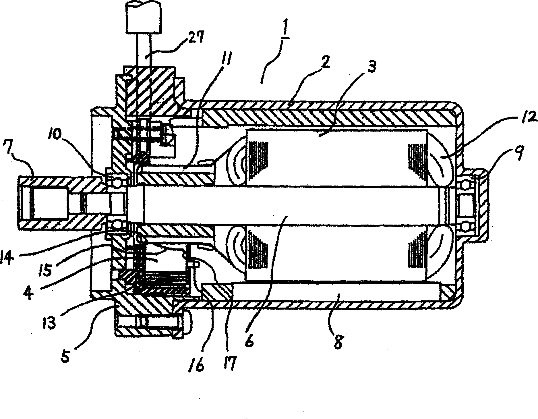
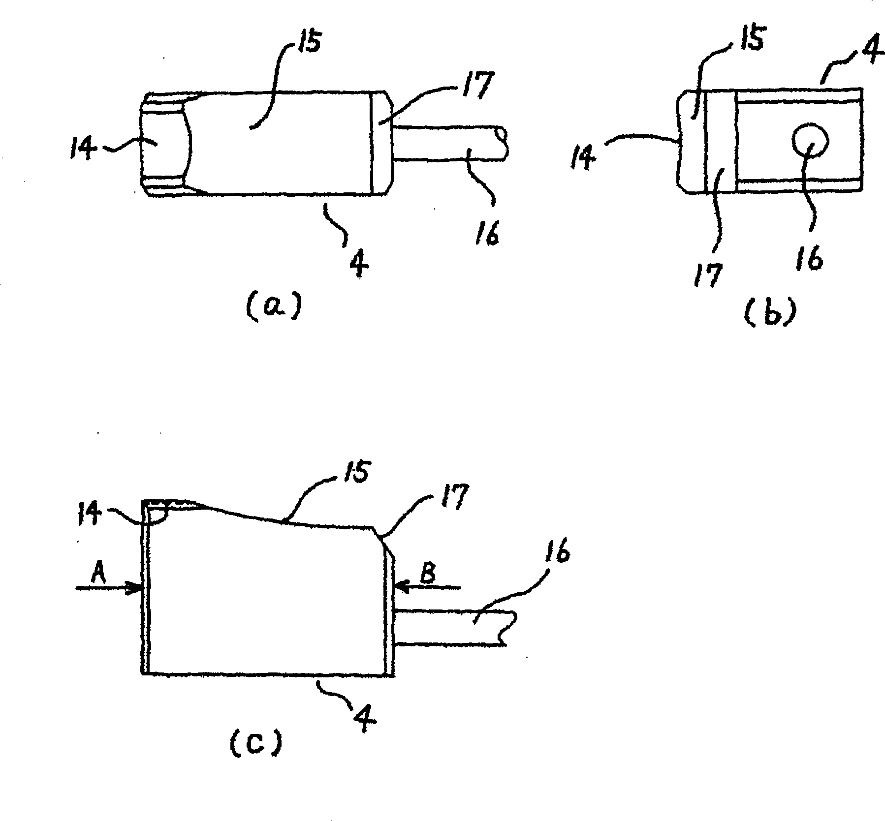
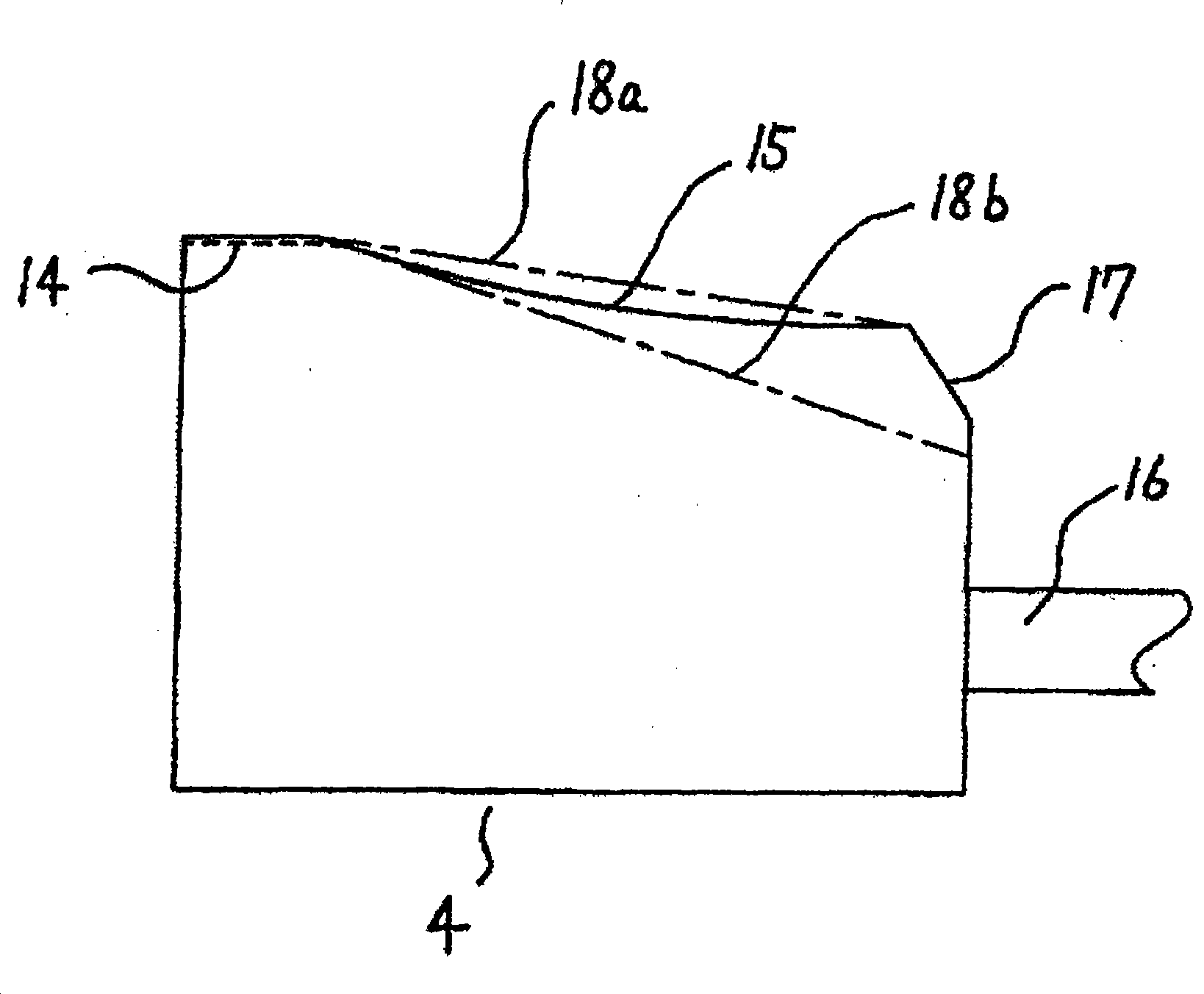
[0022] according to Figure 1 ~ Figure 4 , Embodiment 1 will be described. In addition, in each figure, the same reference numerals are assigned to the same or corresponding parts for description. figure 1 is a sectional view of an electric motor for electric power steering, figure 2 for figure 1 An explanatory diagram of the brush shape of the motor, image 3 for will figure 2 An explanatory diagram comparing the removed part of the brush with the inclined surface of a conventional brush. Figure 4 for figure 2 Explanatory diagram of the formation of the removal part of the brush.

[0023] exist figure 1 Among them, an electric motor 1 for an electric power steering device forming a rotating electric machine has: a bottomed cylindrical yoke 2 forming a stator; an armature 3 forming a rotor disposed inside the yoke 2; Brush 4; end cap 5 fitted into the opening of yoke 2 and fixed to yoke 2; and hub 7 fixed to one end of rotating shaft 6 of a...


PUM


Abstract

The present invention discloses a rotating electric machine and manufacturing method of the electrical brush of the rotating electric machine, which provides a low-cost electrical brush capable of compromising the long life of the electrical brush and shorting the running handling time or having no need of running and processing the two aspects. The rotating electric machine has a glide plane (14) formed on one end of the brush (4) along the concave curved face of the external circumstance surface of a commutator (11); and a removing section(15), formed in a concave curved face in the axial direction, gradually left from the external circumstance surface of the commutator (11) to the other axial direction end of the brush (4) from the glide plane (14), and simultaneously formed a smooth surface without concave-convex in then radial direction at the rotation direction side of the commutator (11). In addition, the method includes a process of continuously performing cutting process to the rotation direction side of the commutator (11) to form a removing section(15).

Description

technical field [0001] The present invention relates to a rotating electrical machine having brushes and a method for manufacturing the brushes. Background technique [0002] As a method related to the production method of the conventional rotating electric machine and its brush for reducing the sliding sound of the brush and the commutator (commutator), there is a method of forming a brush along the inner diameter side surface of the brush. The sliding surface of the concave curved surface of the outer peripheral surface of the commutator; and the inclined surface inclined so that the sliding surface is separated from the outer peripheral surface of the commutator. In such a brush, the inclined surface is formed to conform to the curved surface of the sliding surface The concave curved surface keeps the sliding width of the sliding surface in the motor axial direction substantially constant. In addition, there is a method in which the concave curved surface of the inclined...

Claims


Application Information

Patent Timeline
IPC IPC(8): H02K13/00H01R39/18
CPCH01R39/18H01R43/12H01R43/16H02K13/006H02K15/02
Inventor 和久摄冈崎正文山本雅祥山本京平
Owner MITSUBISHI ELECTRIC CORP
Learn More