Atmosphere plasma cylindrical microwave excitation cavity

A plasma and cylindrical technology, applied in the field of excitation cavity, can solve the problems of complicated structure and increased cost, and achieve the effect of low microwave loss and high conversion efficiency

Inactive Publication Date: 2009-03-04
UNIV OF ELECTRONICS SCI & TECH OF CHINA
View PDF0 Cites 25 Cited by
  • Summary
  • Abstract
  • Description
  • Claims
  • Application Information

AI Technical Summary

Problems solved by technology

Therefore, a quarter coaxial resonant cavity with one end short-circuited and the other end open-circuited, or a standing wave field formed by a compressed waveguide is usually used to increase the microwave electric field at the discharge position. These exciting devices often require an igniter to be installed in an appropriate position Or the ignition pole, in order to generate the initial discharge under a certain microwave power, and then transition to the formation of the entire torch, which complicates the structure of the entire device and increases the cost

Method used


Image

  • Atmosphere plasma cylindrical microwave excitation cavity
  • Atmosphere plasma cylindrical microwave excitation cavity

Examples


Embodiment Construction

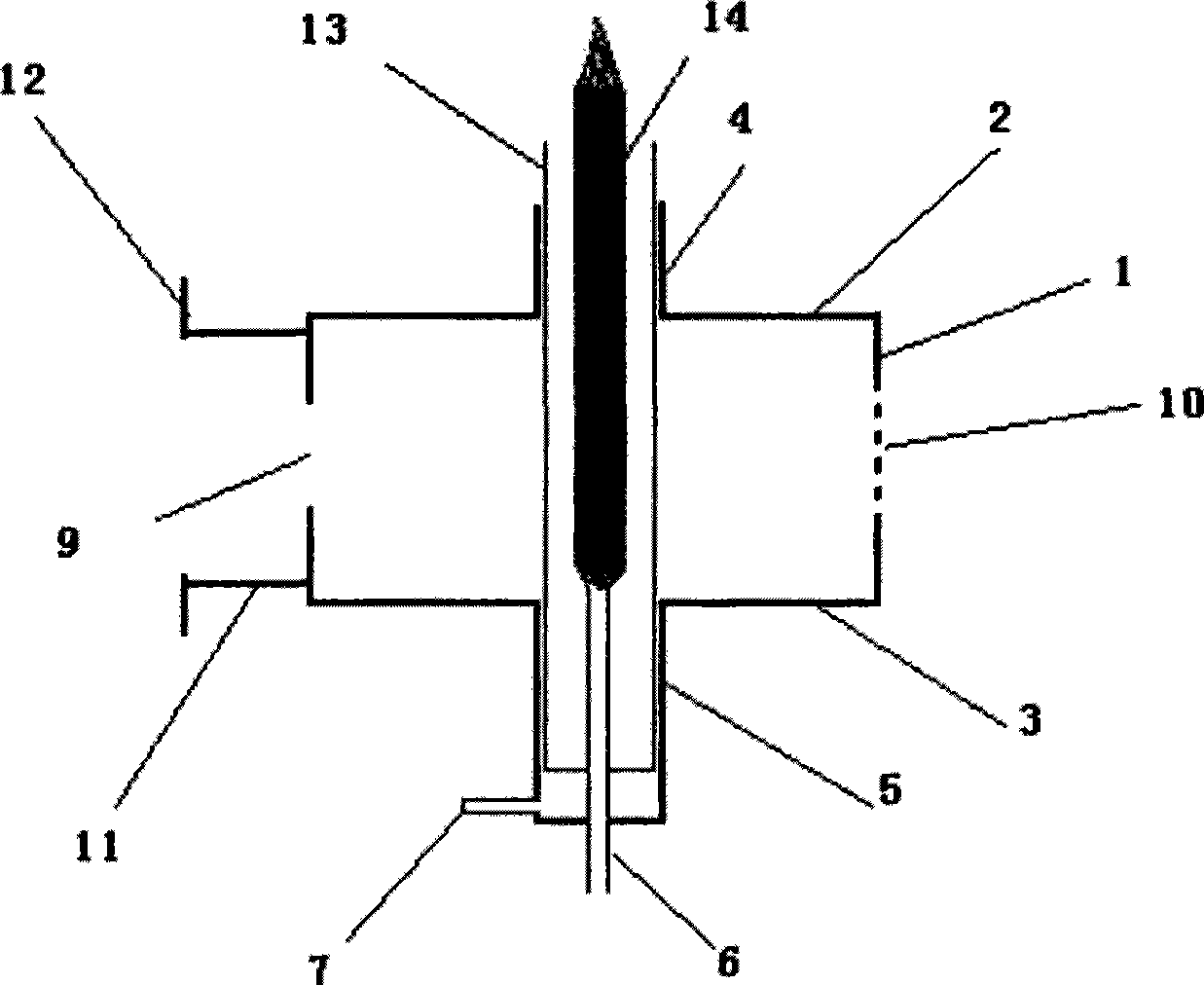
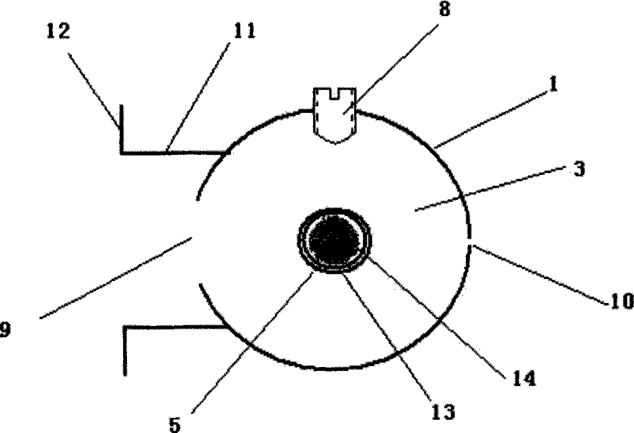
[0017] Attached below figure 1 and 2 The present invention will be further described with implementation case.

[0018] Implementation case structural diagram of the present invention is as figure 1 and figure 2 shown, including: work on TM 010 Model cylindrical cavity cylinder 1, cavity top cover 2, cavity bottom cover 3, cavity top metal cylinder 4, cavity bottom coaxial outer conductor 5, coaxial hollow inner conductor that doubles as a metal nozzle 6. Tangential inlet hole 7 at the bottom of the coaxial outer conductor 5, tuning bolt 8, microwave coupling window 9 between the cylindrical cavity and the outer waveguide, observation hole 10 on the side wall of the cavity, connecting waveguide 11, waveguide flange 12, quartz glass Tube 13, plasma torch 14.

[0019] The specific parameters and dimensions of each part of the structure of this implementation case are as follows:

[0020] This implementation case is based on the working frequency f o = 2450MHz, in order t...


PUM


Abstract

The invention belongs to the field of microwave plasma excitation technique and relates to an excitation chamber without an igniter or ignitor under atmosphere pressure. The excitation chamber comprises a cylindrical resonator which works under a TM<010> mode, an input waveguide and a flange; the cylindrical resonator consists of a cylinder (1), a chamber top cover (2) and a chamber bottom cover (3); the side wall of the cylinder (1) is opened with a micro-wave coupling window (9); a metal cylinder (4) is arranged above the central round hole of the chamber top cover (2); a coaxial external conductor (5) is arranged below the central round hole of the chamber bottom cover (3); the bottom of the coaxial external conductor (5) is provided with a short circuit board which is provided with holes at the center while the bottom of the side wall is provided with a tangent air inlet (7); and the coaxial external conductor (5) is internally provided with a coaxial hollow internal conductor (6) by the central holes. The excitation chamber has low microwave consumption and high conversion efficiency, can excite the atmosphere plasma torch in the chamber without the need of igniters or ignitors under smaller micro-wave powers and can be used for various microwave industries, more specially as the boiler igniter.

Description

technical field [0001] The invention belongs to the technical field of microwave plasma excitation, and in particular relates to the design and use of an excitation cavity without an igniter or an ignition pole under atmospheric pressure or higher than atmospheric pressure. Background technique [0002] Microwave plasma is a quasi-equilibrium low-temperature plasma with high electron density and temperature of non-polar discharge. Compared with DC and RF plasma, it has many advantages and particularities. Therefore, it has been widely used in the past ten years. Applications, especially in microelectronics technology, preparation and synthesis of new materials, aerospace technology, chemical industry, waste treatment, metal refining, packaging materials and pharmaceutical industry, thin film deposition, plasma polymerization, microcircuit manufacturing to welding, tool hardening, Synthesis of ultrafine powder, plasma spraying, plasma metallurgy, plasma chemical industry. Th...

Claims


Application Information

Patent Timeline
Patent Type & Authority Applications(China)
IPC IPC(8): H05H1/30H01J37/32
Inventor 童玲陈彦张兆镗田雨
Owner UNIV OF ELECTRONICS SCI & TECH OF CHINA
Why Eureka
Try Eureka