
Wafer level package of electronic element and manufacturing method thereof

A wafer-level packaging and electronic component technology, applied in electrical components, semiconductor/solid-state device manufacturing, electrical solid-state devices, etc., can solve problems such as peeling, and achieve the effect of improving adhesion and conductivity

Inactive Publication Date: 2009-03-11
XINTEC INC
View PDF2 Cites 2 Cited by
  • Summary
  • Abstract
  • Description
  • Claims
  • Application Information

AI Technical Summary

Problems solved by technology

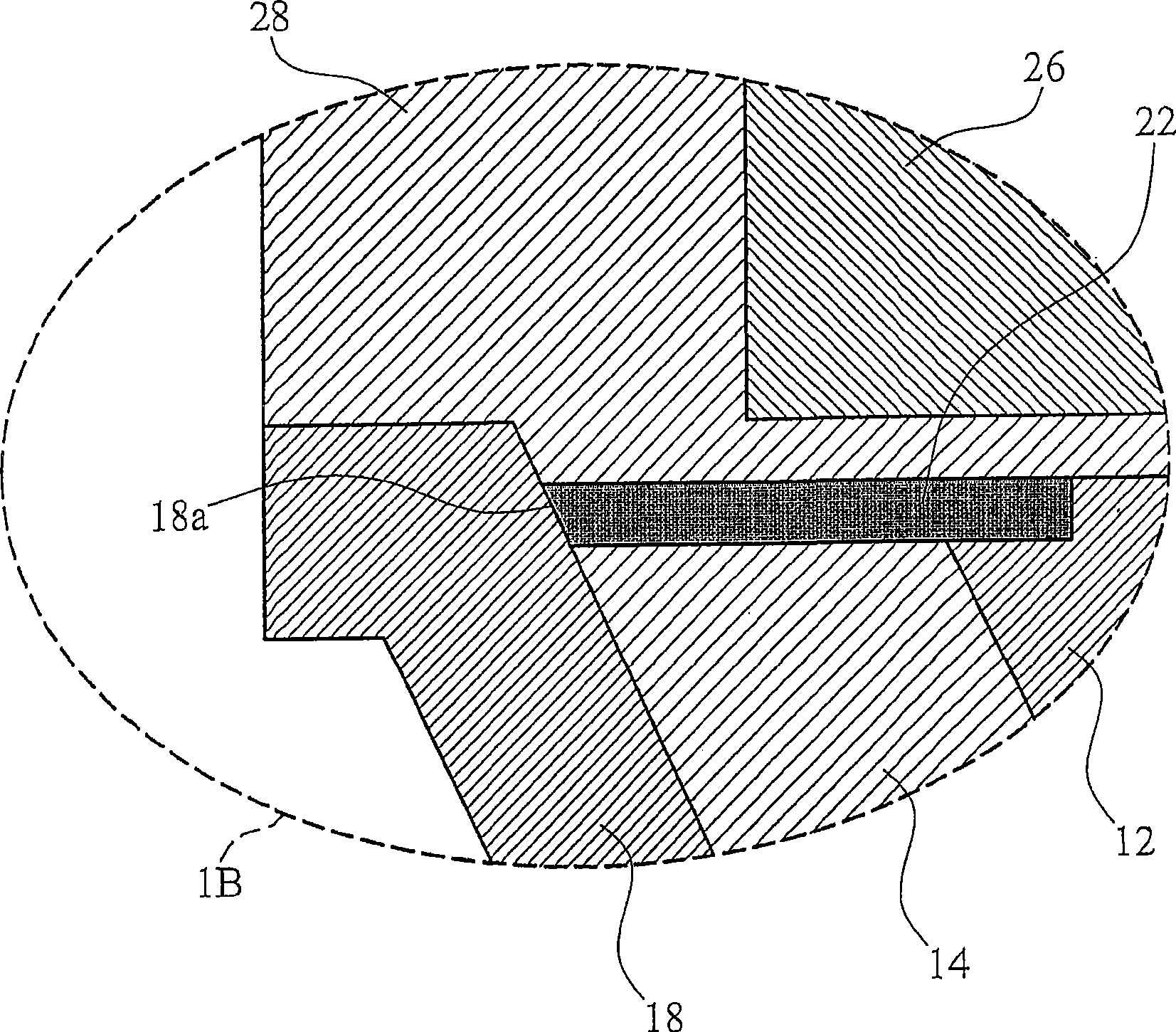
[0005] see Figure 1B , because the contact surface 18a between the wire structure 18 of the T-shaped connection and the contact pad 22 is small, it is easy to cause reliability problems such as peeling

Method used


Image

  • Wafer level package of electronic element and manufacturing method thereof
  • Wafer level package of electronic element and manufacturing method thereof
  • Wafer level package of electronic element and manufacturing method thereof

Examples


Embodiment Construction

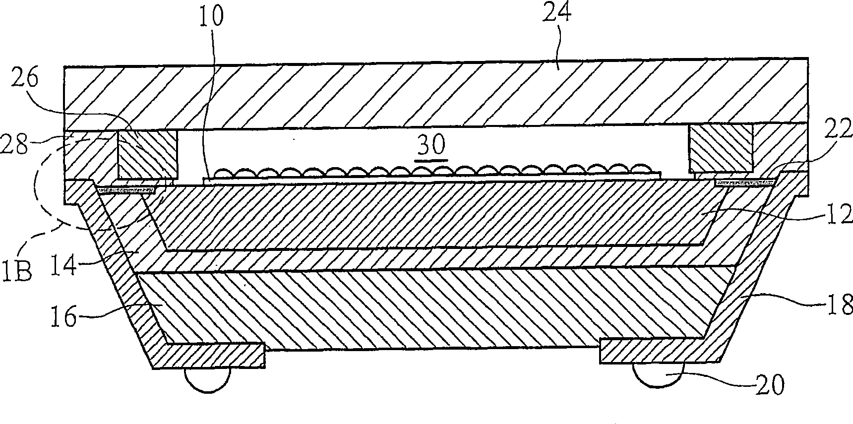
[0043] The following examples are described in detail with various embodiments and accompanying drawings, which serve as a reference basis for the present invention. In the drawings or descriptions in the specification, the same reference numerals are used for similar or identical parts. And in the drawings, the shapes or thicknesses of the embodiments may be enlarged for simplification or convenient labeling. In addition, the parts of each element in the drawings will be described separately. It should be noted that the elements not shown or described in the drawings are forms known to those skilled in the art. In addition, the specific embodiment is only The disclosure of a specific method used in the present invention is not intended to limit the present invention.

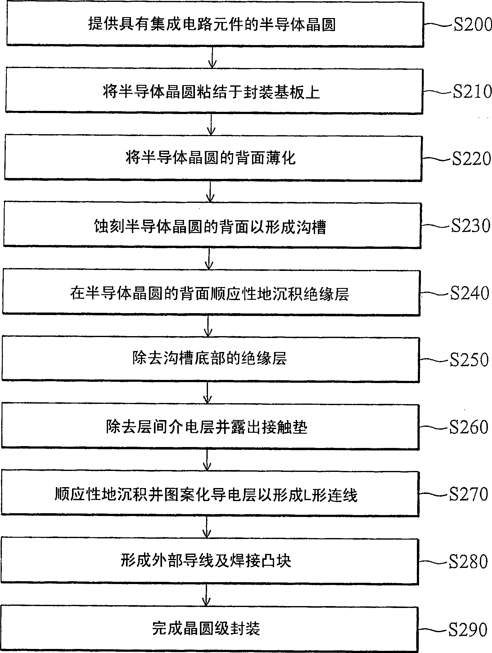
[0044] figure 2A flowchart showing a method for manufacturing wafer-level packaging of electronic components according to an embodiment of the present invention. First in step S200, a semiconductor wafer wi...


PUM


Abstract

The invention provides a wafer grade encapsulating device of an electronic component and a manufacturing method thereof. The manufacturing method of the wafer grade encapsulating device of the electronic component comprises the following steps: a semiconductor wafer is supplied and comprises a plurality of electronic component chips, the semiconductor wafer and a bearing base plate are bonded, the back surface of the semiconductor wafer is thinned and is etched to form a groove, an insulating layer is deposited on the back surface of the semiconductor wafer in an adaptability mode, the insulating layer which is arranged at the bottom of the groove is removed, an interlaminar dielectric layer which is arranged at the bottom of the groove is removed, the partial surfaces of a pair of contact cushions are exposed, and a conducting layer is deposited on the back surface of the semiconductor wafer in an adaptability mode; after the semiconductor wafer is patterned, the semiconductor wafer and the contact cushions form an L-shaped connection, and an external conducting wire and a welding bump are formed. The invention can improve the adhesive property and the electric conductivity between the conducting wire structure and the contact cushions.

Description

technical field [0001] The invention relates to wafer-level packaging of electronic components, in particular to a wafer-level packaging of a CMOS image sensor and a manufacturing method thereof. Background technique [0002] Complementary metal-oxide-semiconductor field-effect transistor image sensors (CMOS image sensors) have been widely used in many application fields, such as digital still cameras (digital still cameras, DSCs). The above application fields mainly utilize active pixel arrays or image sensor cell arrays, including photodiode elements, to convert incident image light energy into digital data. [0003] A conventional chip scale package (CSP) for electronic components is designed for flip chip bonding on a carrier substrate such as a package substrate, a module substrate, or a printed circuit board (PCB). During the flip-chip bonding process step, it is necessary to bond soldering bumps, soldering studs or terminals on other packaged objects to matching cont...

Claims


Application Information

Patent Timeline
Patent Type & Authority Applications(China)
IPC IPC(8): H01L21/60H01L23/482H01L27/146
CPCH01L2924/0002H01L2224/13
Inventor 刘建宏李思典
Owner XINTEC INC
Learn More