
Wireless relay system and data transmission method

A data transmission method and wireless relay technology, applied in the wireless relay system and the field of data transmission, can solve the problems of data transmission failure, inability to match MAC PDUs, affecting system performance, etc.

Active Publication Date: 2009-03-11
ZTE CORP
View PDF0 Cites 41 Cited by
  • Summary
  • Abstract
  • Description
  • Claims
  • Application Information

AI Technical Summary

Problems solved by technology

Due to the independence of BS and RS in managing wireless resources, the time-varying nature of wireless signals, and the differences in wireless environments between BS and RS and between RS and UT, MAC PDUs transmitted between BS and RS and between RS and UT usually cannot Matching, resulting in failure of data transmission through RS, seriously affecting system performance

Method used


Image

  • Wireless relay system and data transmission method
  • Wireless relay system and data transmission method
  • Wireless relay system and data transmission method

Examples


Embodiment 1

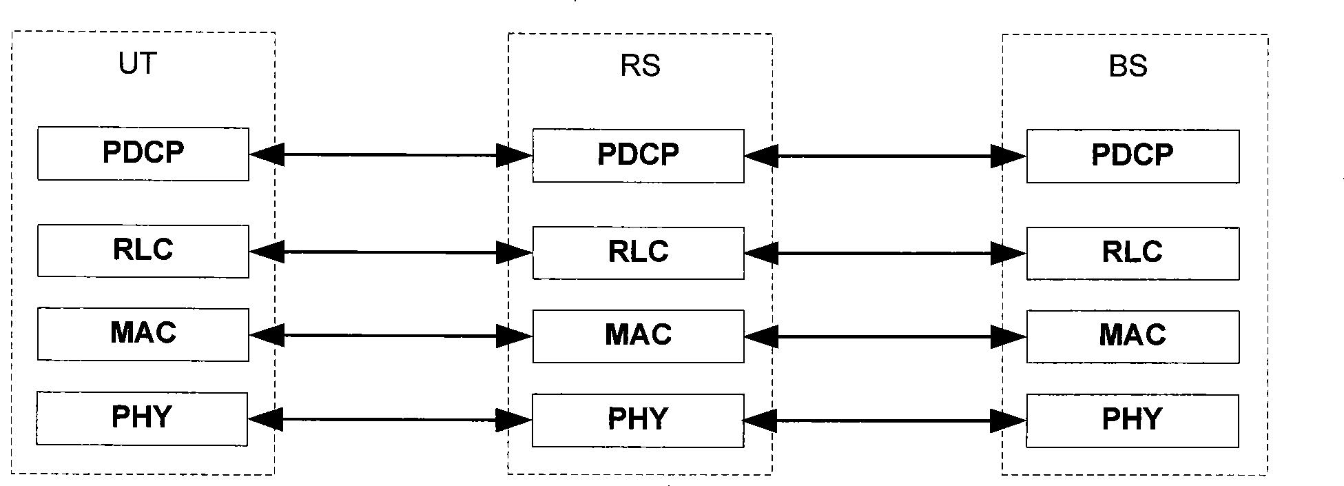
[0044] The wireless relay system of the present invention includes BS, UT and RS, and the respective protocol stack frameworks of BS, UT and RS are as follows: Figure 4 As shown, both BS and UT include PDCP entity, RLC entity, MAC entity and PHY entity, while RS only includes physical layer PHY entity and medium access control layer MAC entity. The BS and UT perform peer-to-peer data transmission on the RLC protocol layer and the PDCP protocol layer, while the BS and UT implement peer-to-peer data transmission with the RS on the PHY protocol layer and the MAC protocol layer respectively.

[0045] The MAC entity of the RS receives the MAC PDU from the MAC entity of the BS or UT, and analyzes the MAC PDU, caches the MAC SDU in it, and determines the length of the MAC protocol data unit that can be sent currently when sending the cached data, and takes out the MAC PDU according to the length One or more buffered MAC SDUs form a MAC PDU, which is sent to the destination UE or the...

Embodiment 2

[0062] The system architecture based on this embodiment is the same as that of Embodiment 1. BS and UT perform peer-to-peer data transmission on the RLC protocol layer and PDCP protocol layer, while BS and UT implement the PHY protocol layer and MAC protocol layer with RS respectively. Peer layer data transfer.

[0063] The medium access control layer MAC entity in the RS is different from Embodiment 1, and further includes:

[0064] The receiving unit is configured to receive the MAC PDU sent from the MAC entity of the base station or the user end to be sent to the user end or the base station, and trigger the judging unit to process it.

[0065]The judging unit is used for judging, for each user terminal (including data to be sent to the user terminal and data sent from the user terminal), according to the length of the MAC PDU that can be sent at present, the MAC PDU received from the base station or the user terminal to be sent to Whether the MAC protocol data unit of the...


PUM


Abstract

The invention discloses a wireless relay system and the data transmission method thereof, which belong to the filed of wireless communication. The method of the invention includes the steps: first, a media access control layer (MAC) entity of a wireless relay station receives an MAC protocol data unit to be sent to a user terminal or a base station for the base station or the user terminal; then the MAC entity of the wireless relay station defines the length of the MAC protocol data unit which can be sent at present, analyzes the MAC protocol data unit which cannot be transmitted to the destination user terminal or the base station once and takes out the MAC protocol data unit to cache; finally, when the MAC entity of the wireless relay station sends the cached data, one or a plurality of MAC service data unit(s) is / are taken out to compose the MAC protocol data unit which conforms to the length requirement, and then the MAC protocol data unit is sent to the MAC entity of the destination user terminal or the base station. The invention also provides the wireless relay system, improves the success ratio for data transmission between BS and UT and the utilization ratio of wireless resources.

Description

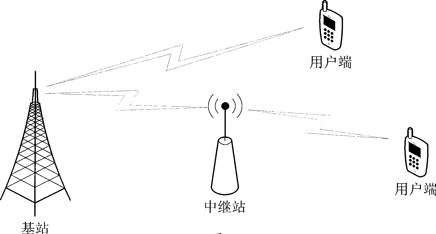
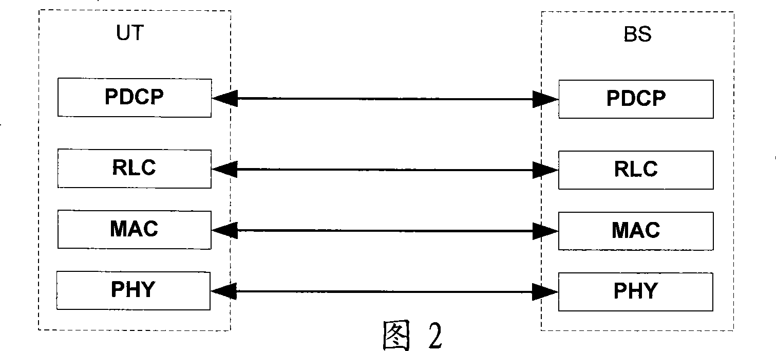
technical field [0001] The invention belongs to the field of wireless communication, in particular to a wireless relay system and a data transmission method thereof. Background technique [0002] The framework of a radio access network (Radio Access Network) is mainly composed of multiple base stations (BS) and user terminals (UT). Under power, the signal can completely cover a specific area. However, when planning the coverage of the base station, it is necessary to consider the shadow fading effect of the signal caused by terrain and features, so that the effective coverage needs to be greatly reduced to ensure that the user terminal still has a certain connection probability when the signal suffers from severe shadow fading. [0003] Therefore, the concept of reducing the effect of shadow fading through signal relay came into being. Its model is as follows figure 1 As shown, the wireless relay station RS (Relay Station) is introduced into the wireless access network, an...

Claims


Application Information

Patent Timeline
Patent Type & Authority Applications(China)
IPC IPC(8): H04Q7/30H04B7/14H04L29/06H04L29/08
Inventor 张银成曾清海李姣姚翠峰
Owner ZTE CORP
Learn More