A device and a method of manufacturing a housing material
A technology of equipment and casing, which is applied in the field of manufacturing casing materials, can solve problems such as the influence of magnetic shielding materials, and achieve the effect of improving the overall strength
- Summary
- Abstract
- Description
- Claims
- Application Information
AI Technical Summary
Problems solved by technology
Method used
Image
Examples
Embodiment approach 2
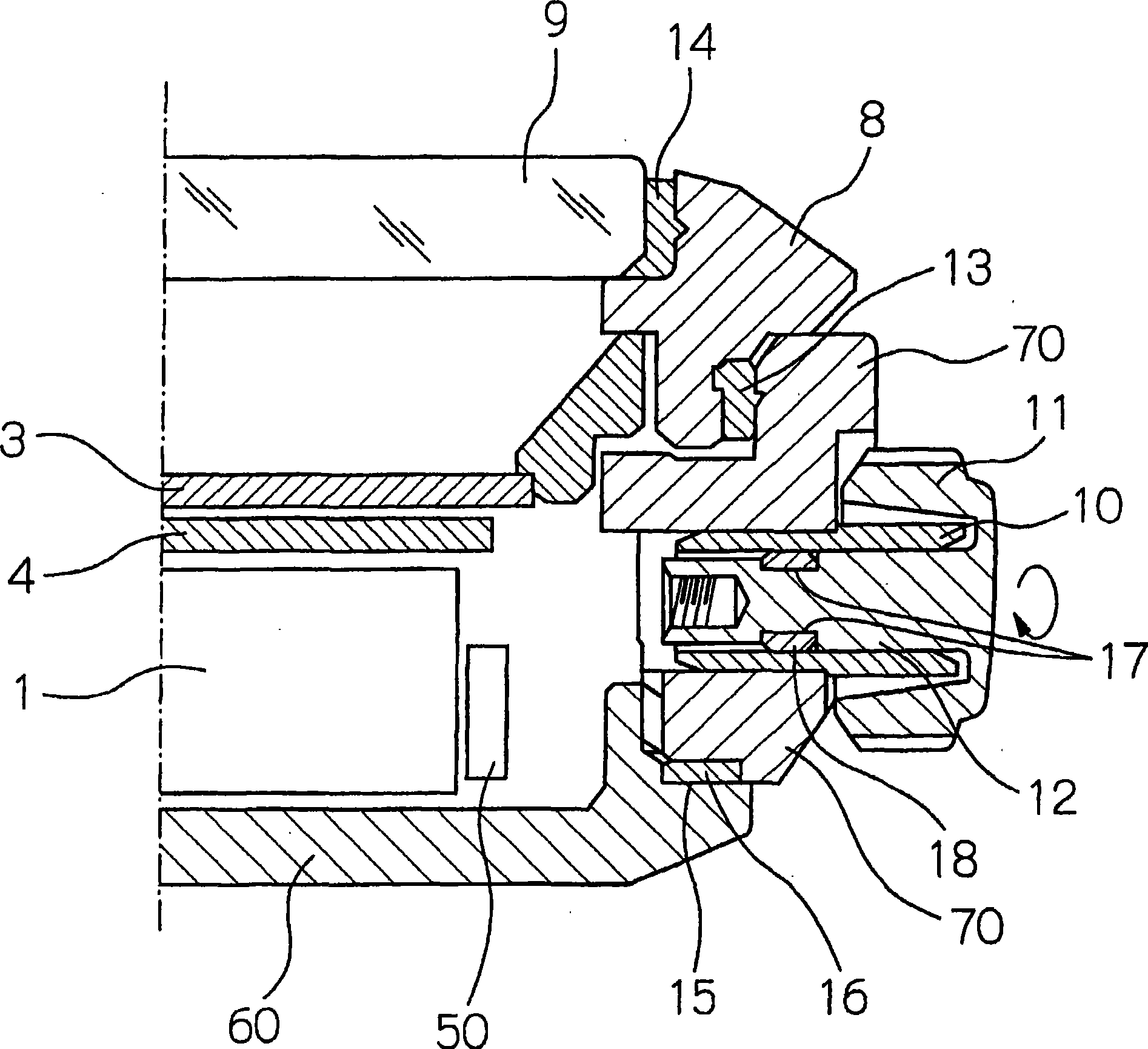
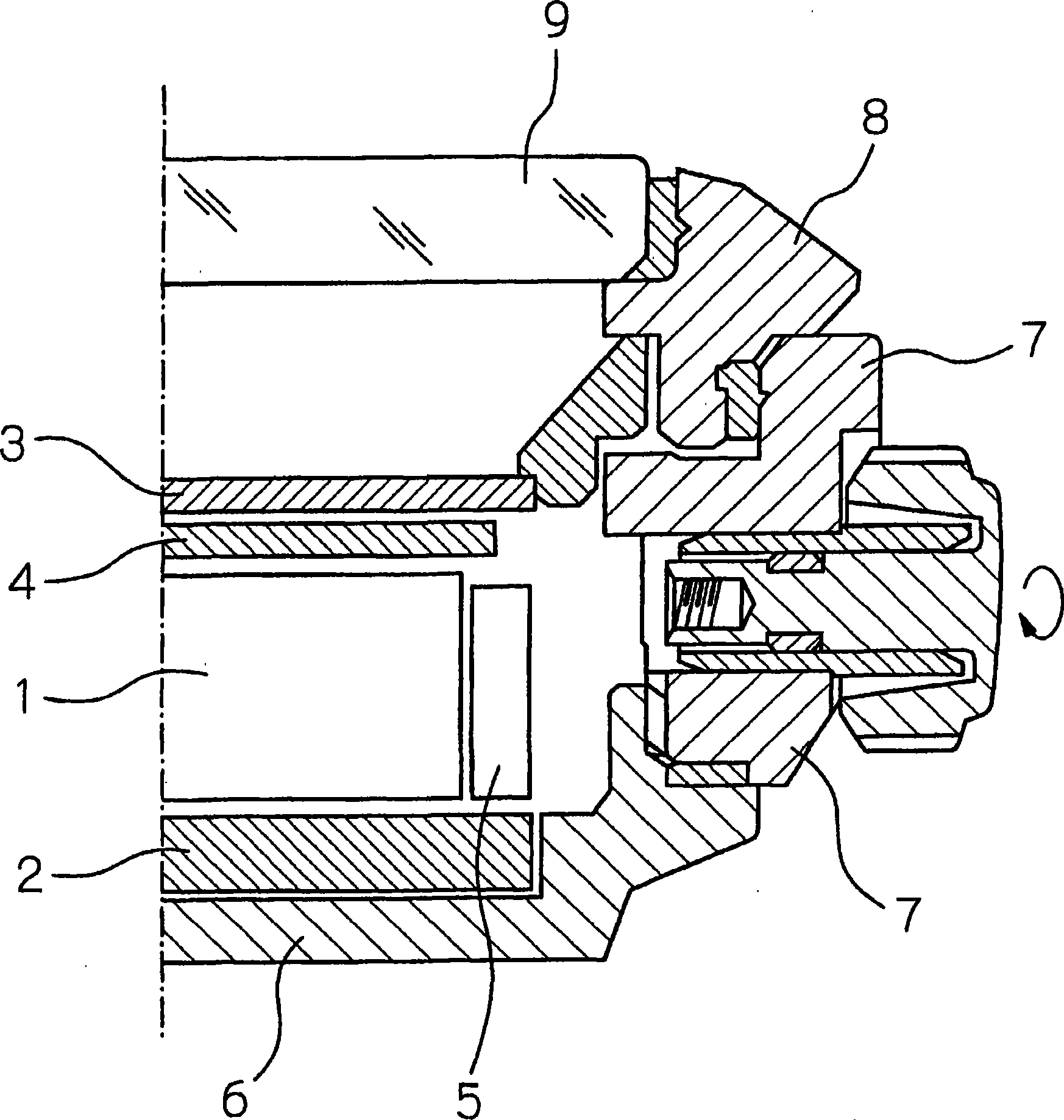
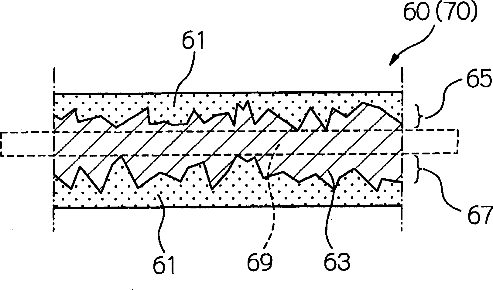
[0055] In Embodiment 1 above, the casing (the rear cover 60 and the cabinet 70) is based on ferritic stainless steel, and the surface is austenitized by adding nitrogen atoms from the surface of the base material. The layer 61 is formed in a state where the ferrite phase inner layer portion 63 is left, and can also be produced as follows.
[0056] A shell of a desired shape is fabricated from ferritic stainless steel, and the shell is austenitized as a whole by absorbing nitrogen atoms from the surface, and then transformed into austenite single-phase by rapid cooling. Then, after raising the temperature of the austenite single phase, it is cooled at a cooling rate at which chromium nitride is formed. Thus, if Figure 5 It is schematically shown that the interior can be restored to the ferrite phase inner layer portion 63 while the surface remains as the austenitized surface layer 61 . Figure 5 It shows a state where the amount of ferrite phase recovered from the austenite ...
Embodiment 1
[0094] The case (the back cover of the watch) was manufactured by the method shown below.
[0095] First, a Fe—Cr-based ferritic stainless steel base material containing Fe as a main component is prepared. The substrate has such components: Fe—18.3wt%, Cr—2.25wt%, Mo—0.15wt%, Nb—0.26wt%, Mn—0.006wt%, C—0.001wt%, S—0.022%, P—0.21wt%, Si, mainly composed of ferrite phase. In addition, the content of each element contained as an unavoidable impurity other than that is less than 0.001 wt%.
[0096] Next, using this base material, a base material having the shape of a watch back cover is produced by forging, and necessary parts are cut and ground.
[0097] Next, the substrate is cleaned. For cleaning of the base material, first, alkaline electrolytic degreasing was performed for 30 seconds, and then alkaline immersion degreasing was performed for 30 seconds. Then, neutralization for 10 seconds, water washing for 10 seconds, and pure water washing for 10 seconds were performed. ...
Embodiment 2~7
[0106] Examples 2 to 7 differ from Example 1 only in that the composition of the Fe—Cr-based ferritic stainless steel constituting the base material and the conditions of the austenitizing treatment are as shown in Table 1. Except for this difference, the back cover of the watch was produced in the same manner as in the first embodiment.
PUM
| Property | Measurement | Unit |
|---|---|---|
| particle diameter | aaaaa | aaaaa |
| particle diameter | aaaaa | aaaaa |
| diameter | aaaaa | aaaaa |
Abstract
Description
Claims
Application Information
 - R&D
- Intellectual Property
- Life Sciences
- Materials
- Tech Scout
- Unparalleled Data Quality
- Higher Quality Content
- 60% Fewer Hallucinations
Browse by: Latest US Patents, China's latest patents, Technical Efficacy Thesaurus, Application Domain, Technology Topic, Popular Technical Reports.
© 2025 PatSnap. All rights reserved.Legal|Privacy policy|Modern Slavery Act Transparency Statement|Sitemap|About US| Contact US: help@patsnap.com


