Vision prosthesis device based on optical-disc micro-electrode array

A micro-electrode array and visual prosthesis technology, applied in the field of medical devices, can solve the problems of not solving the efficiency and practicality of electrical nerve stimulation, not taking into account the fixing method of the electrode array, and the small number of electrodes in the stimulating electrode array, etc. Biocompatibility, restoration of visual function, low risk effects

Inactive Publication Date: 2011-06-29
SHANGHAI JIAOTONG UNIV
View PDF1 Cites 5 Cited by
  • Summary
  • Abstract
  • Description
  • Claims
  • Application Information

AI Technical Summary

Problems solved by technology

Visual cortical prostheses, because people's understanding of the brain is not very sufficient, so the potential risk factors of implanting stimulating electrode array surgery on the visual cortex are also relatively large, there are certain risks, and it is easy to cause certain psychological pressure on patients
[0004] Found through the retrieval of prior art document, the U.S. patent of application on September 27th, 2007, the patent application number is US 2007 / 0225775A1, and the patent title is " Vision Regeneration Assisting Device " (visual function restoration device) also proposes to carry out on the optic disc. A visual prosthetic device for electrical stimulation, but the number of electrodes in the stimulating electrode array in this technology is small and the length of the electrodes is the same, which does not take into account the stimulation of nerve fibers at different positions and depths when used on the optic disc, and does not consider The fixing method of the electrode array does not solve the efficiency and practical problems of electrical stimulation of nerves, so the overall performance of the electrode array needs to be further improved

Method used


Image

  • Vision prosthesis device based on optical-disc micro-electrode array
  • Vision prosthesis device based on optical-disc micro-electrode array
  • Vision prosthesis device based on optical-disc micro-electrode array

Examples


Embodiment Construction

[0031] The embodiments of the present invention are described in detail below in conjunction with the accompanying drawings: this embodiment is implemented on the premise of the technical solution of the present invention, and detailed implementation methods and specific operating procedures are provided, but the protection scope of the present invention is not limited to the following the described embodiment.

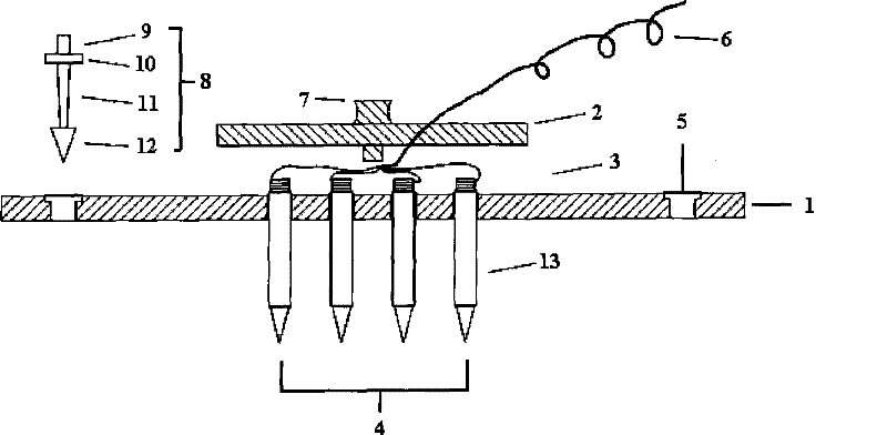
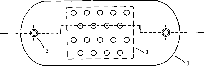
[0032] Such as figure 1 , figure 2As shown, this embodiment includes: a microelectrode array substrate 1, a cover plate 2, a microelectrode array 4, electrode wires 6 and retinal pins 8, wherein,

[0033] The two ends of the microelectrode array substrate 1 are respectively provided with a retinal pin via hole 5, and the middle position is provided with 18 electrode via holes, and the retinal pin 8 passes through the retinal pin via hole to fix the micromotor array base 1 on the optic disk 15 of the retina, The microelectrode array 4 is composed of 18 electrode wir...


PUM


Abstract

A visual prosthetic device is based on videodisc microelectrode array, belonging to the technical field of medical appliance. The device comprises a microelectrode array substrate, a microelectrode array and an electrode cable, and is characterized by further comprising a cover board and a retina nail; wherein, the two ends of the microelectrode array substrate are respectively provided with a through hole of the retina nail, the middle of microelectrode array substrate is provided with 18 electrode through holes, and the retina nail passes through the through hole of the retina nail to fix the microelectrode array substrate on a videodisc of the retina; the microelectrode array consists of 18 wire electrodes which are fixed in the electrode through holes that are arranged in the center of the microelectrode array substrate, one ends of the wire electrodes are connected in vitro by the electrode cables, and the cover board covers above the electrode through holes of the microelectrodearray substrate to fix the microelectrode array. The visual prosthetic device is applied for generating artificial vision and is the medical device for helping the retina blindness patients to gain brightness and vision again.

Description

technical field [0001] The invention relates to a device in the technical field of medical instruments, in particular to a visual prosthesis device based on an optic disc microelectrode array. Background technique [0002] A visual prosthesis is a medical device that helps patients with retinal or other visual organ lesions regain light and vision. The formation of normal vision is that the photoreceptor cells (cones and rods) on the retina convert light stimulation into electrical signals. The axonal continuation of the ganglion cells, the optic nerve, transmits nerve impulses to the visual cortex. Therefore, the current design of visual prosthetic devices is to implant electrodes into various organs of the visual pathway, that is, on the retina, optic nerve or visual cortex, and the electrode array directly acts on these central and peripheral nerves with encoded electrical signals in the form of specific pulses. system that simulates the normal formation of vision. [...

Claims


Application Information

Patent Timeline
Patent Type & Authority Patents(China)
IPC IPC(8): A61F9/08A61N1/36
Inventor 陆一樑任秋实吴开杰隋晓红许迅
Owner SHANGHAI JIAOTONG UNIV
Why Eureka
Try Eureka