Connection method of filtering filter-core and machine base

A connection method and machine base technology, applied in the direction of loose filter material filter, filtration separation, separation method, etc., can solve the problems of improving the filtering effect, affecting the life of the filter element, clogging, etc., achieving easy quality control, improving product quality, The effect of reducing the cost of use

Inactive Publication Date: 2009-04-01
杜也兵
View PDF0 Cites 3 Cited by
  • Summary
  • Abstract
  • Description
  • Claims
  • Application Information

AI Technical Summary

Problems solved by technology

However, with the popularization of water treatment machines, their defects and deficiencies in application have gradually been exposed.
For the open filter element, various granular filter materials such as KDF and activated carbon are usually placed inside the filter gall. Due to the different contact time between the water flow in the filter element and the filter material in the filter layer, the upper part of the filter layer has a worse effect on water flow treatment than the lower part. , resulting in uneven and stable water quality
Since the shell is screwed tightly on the machine base, the multi-water filter element mode cannot be used to improve the filtering effect
When manufacturing and assembling, the screw connection of the machine base is prone to water leakage
And the screw-in connection method can only be a single-channel pipeline connection, resulting in the water inlet and outlet being located at the front and rear ends of the water purifier, resulting in unchanged use and affecting the appearance
In the process of use, it is laborious to replace the filter tube, and a special wrench is required
As for the closed filter element, although the treatment effect of the filter layer is better, it is more troublesome to replace the filter element, and professional maintenance personnel are required to provide door-to-door service, which will increase manpower and financial resources accordingly.
In addition, after the filter element is used for a period of time, the filter material of the filter element is gradually clogged or adsorbed by impurities, resulting in a significant decrease in the filtering and adsorption effects.
Moreover, as more and more impurities are intercepted by the filter element, the "pollution" degree of the filter element impurities will often exceed the "pollution" degree of the drinking water itself, so that the filter element becomes a new "pollution" source
Especially in some water purifier filter elements using ultrafiltration membrane, nanofiltration membrane, and reverse osmosis membrane, due to the extremely small pore size of the screen, it is easy to cause clogging during use, which affects the life of the filter element
However, it is difficult to set the filter element with two outlets into a combination of multiple filter layers, especially for water treatment machines with two-end screen-type filter material and intermediate particle filter material mode, it is difficult to accumulate the middle and permeate on the rear-stage screen by using the reverse full backwash mode After passing through the multi-stage filter element, the impurities are completely discharged from the water inlet, and the intermediate impurities are often washed back and forth in the forward and reverse directions and cannot be discharged; while the water treatment machine with layered or graded separate "backflush" function requires both water flow To switch the direction, it is necessary to configure the corresponding multi-water outlet filter element
It in turn has a great impact on the structure of conventional filter elements and the mode of installation and replacement
The above-mentioned defects and deficiencies make it difficult for water treatment machines to be more widely popularized

Method used


Image

  • Connection method of filtering filter-core and machine base

Examples


Embodiment Construction

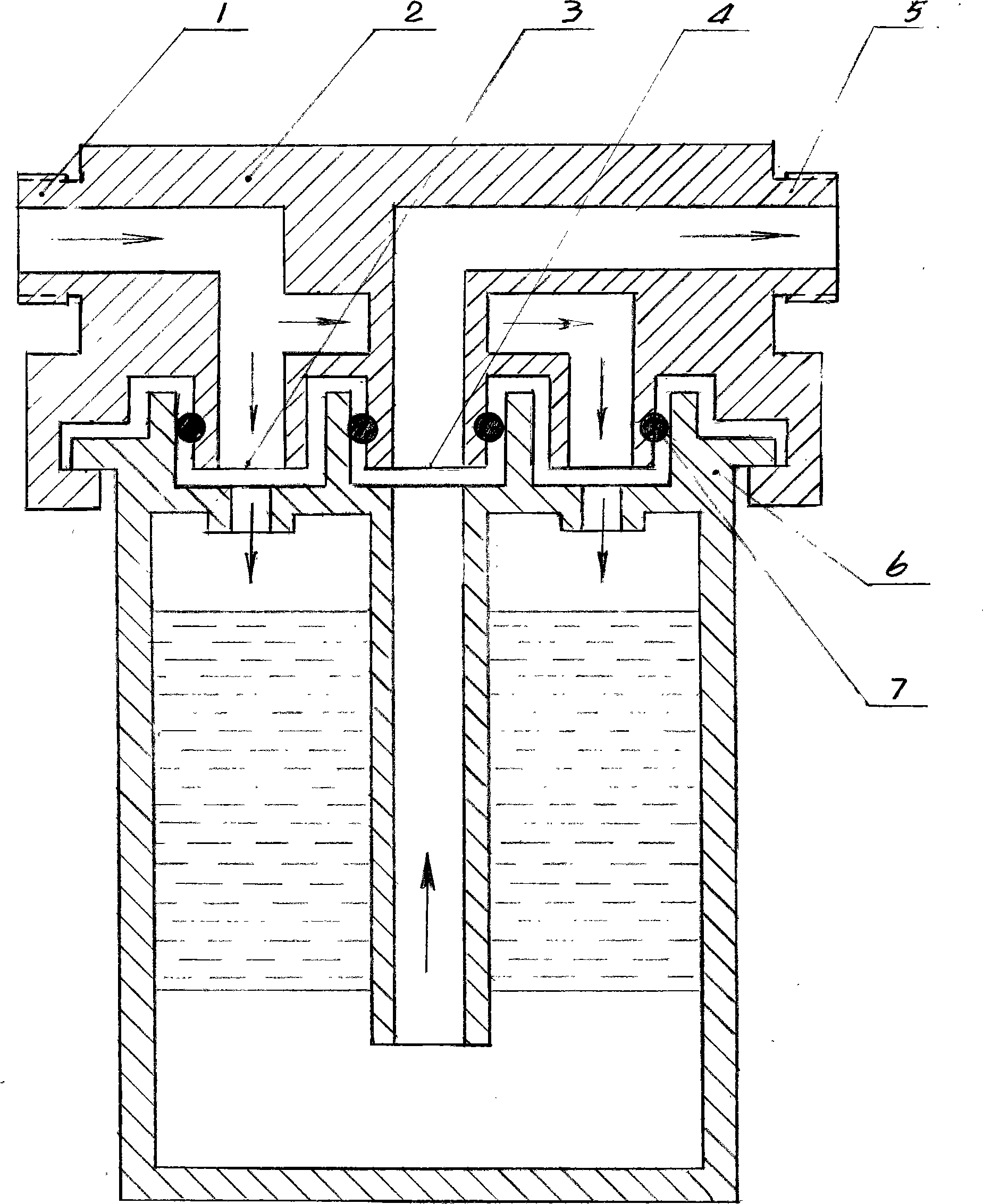
[0017] The preferred embodiment of the invention is shown in the accompanying drawings. The concave-convex disc-shaped water inlet and outlet of the support 2 and the corresponding concave-convex disc-shaped water inlet and outlet on the closed filter element 6 are connected to each other, and are sealed with seals 7 of different sizes to prevent water leakage in each nozzle. The disc-shaped docking nozzle of the support 2 and the filter element 6 is an annular nozzle with the central nozzle of the disc as the center of the circle. The water inlet located on the outer side is a ring-shaped porous structure, which ensures that the central water outlet on the inner side has sufficient connection structure strength to be integrated with the machine base. The group of disc-shaped water ports communicates with the machine base and the water inlet and outlet channels of the filter element, so that the filter element 6 is connected in series between the inlet and outlet pipe interfac...


PUM


Abstract

The invention relates to water treatment industry, in particular to the depth-type filtration and purification of drinking water. The invention comprises a pipeline interface used for connecting the inlet water and the outlet water, an engine seat which is connected between the interfaces of a water inlet pipeline and a water outlet pipeline and is provided with circular water gaps and a closed filter element that is provided with circular water gaps and can be fixed on the engine seat in a self-rotation way; wherein, all the circular water gaps of the closed filter element are in abutting joint and matched with that of the engine seat, and a sealing element is arranged between the closed filter element and the engine seat. The invention has the advantages of simple assembly of the filter element, easy control of the quality and convenient replacement. By adopting the filter element with a plurality of circular water gaps, the filter element can be designed into a combination with multilevel filtering layers, thus improving the filtration effect and the quality of the products. As the filter element is very easy to replace by the self of the user, the service expense caused by visit of professional for replacing the filter element at the home of the user is avoided, thus relatively reducing the using cost of the filter element.

Description

technical field [0001] The invention relates to the water treatment industry, and specifically relates to the deep filtration and purification of drinking water. Background technique [0002] At present, water treatment machines are relatively popular in China. When in use, the water treatment machine is used to deeply filter the impurities in the water and water pipelines, which better protects the health of users. Water treatment machines usually use two filter modes. One is an open filter gall: the filter gall is cylindrical without a shell. The water inlet and outlet are both set on the machine base, and the shell put into the open filter is screwed tightly on the machine base to form a closed filter element. The water flow enters through the top filter channel and passes through the outer side of the cylindrical filter layer, and then passes through the filter layer and then passes through the filter layer. The water outlet of the filter channel flows out. And the f...

Claims


Application Information

Patent Timeline
Patent Type & Authority Applications(China)
IPC IPC(8): B01D24/12
Inventor 杜也兵
Owner 杜也兵
Why Eureka
Try Eureka