
Double-crank shaft engine

A technology of engine and double crankshaft, which is applied in the direction of machines/engines, mechanical equipment, one-way clutches, etc., can solve problems such as large crankshaft, reduced fuel consumption, increased engine effective power and torque, etc., to increase the length of the arm and reduce the Fuel consumption, effect of improving effective power and torque

Inactive Publication Date: 2009-04-01
宋永义
View PDF0 Cites 2 Cited by
  • Summary
  • Abstract
  • Description
  • Claims
  • Application Information

AI Technical Summary

Problems solved by technology

[0003] In order to overcome the shortage in the prior art that the crankshaft cannot produce a correspondingly large rotational force when the engine is working when the air pressure in the cylinder is high, the present invention provides a double crankshaft engine. When the double crankshaft engine is working, the piston is at the top dead center position, which can The force that makes the crankshaft rotate is generated, and the section where the gas expansion pressure is the largest is also the section that makes the crankshaft generate the maximum rotational force, and the radius of the crankshaft is increased when doing work, that is, the length of the arm is increased, the effective power and torque of the engine are increased, and the fuel consumption is reduced. reduce

Method used


Image

  • Double-crank shaft engine
  • Double-crank shaft engine
  • Double-crank shaft engine

Examples


Embodiment Construction

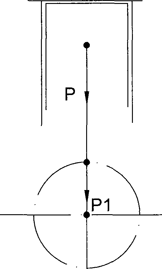
[0017] Such as Figure 4 Shown, a kind of dual crankshaft engine comprises a cylinder (6) and a piston (4) assembled in the cylinder (6), and the top of the cylinder (6) is closed with a cylinder head (2). On cylinder head (2), be equipped with inlet and exhaust device (1) and fuel supply device (not shown in the figure), if ignition type engine also comprises a spark plug (3) of timely ignition. Piston (4) is hinged with the upper end of connecting rod (7) through piston pin (5). Wherein the cylinder (6), piston (4), connecting rod (7), cylinder head (2) and the intake and exhaust device (1) and fuel supply device, spark plug (3) on the cylinder head (2), its structure And the cooperative relationship between each part is the same as the prior art, so I won't repeat it here.

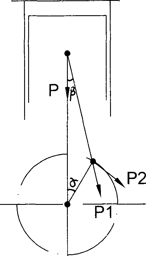
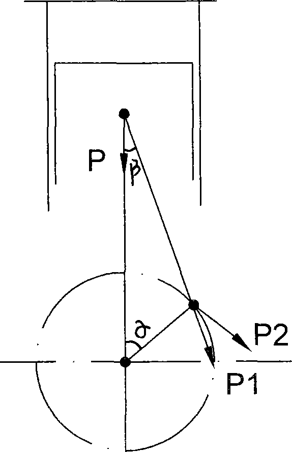
[0018] Figure 4 In, also comprise a crankcase (8), a crankshaft (18) is supported and assembled in the crankcase (8) by the bearing (17), the feature of the present invention is: the crank pin (19) ...


PUM


Abstract

The invention relates to a twin crankshaft engine which comprises a cylinder, a piston and a crankcase. An air intake device, an air exhausting device and a fuel supply device are arranged on a cylinder head. The piston is articulated with the upper end of a connecting rod by a piston pin and a crank shaft is installed in the crankcase by a bearing. The twin crankshaft engine is characterized in that: a crank pin of the crank is fixedly connected with an inner sheath of a one-way clutch while an outer sheath of the one-way clutch is provided with a connecting convex plate. The lower side of the connecting rod is articulated with the connecting convex plate by a pin roll. An auxiliary crank shaft is installed in the crankcase by the bearing and a rotating component is fixedly connected on a crank pin of the auxiliary crank shaft. The shell of the rotating component is fixedly connected with the outer sheath of the one-way clutch by a plate spring. The same rotating direction, rotating speed and radius of turn of the crank shaft and the auxiliary crank shaft are realized by a transmission component. When the engine applies work, the piston is positioned at an upper dead point so as to be capable of generating a force for causing the crank shaft to rotate. The maximum interval of gas expansion pressure is also the maximum interval causing the crank shaft to generate the maximum rotating force. When work is applied, the crank radius is increased so as to improve the effective power and the torsional moment of the engine and reduce the fuel consumption.

Description

technical field [0001] The invention relates to other engines, in particular to a double-crankshaft engine capable of performing work at the top dead center and increasing the radius of the crankshaft when performing work. Background technique [0002] We know that an engine is a machine that converts the heat energy released by the combustion of fuel and air in the cylinder into mechanical work. Existing reciprocating piston engines all have a work cycle consisting of intake air, compression, work, and exhaust four processes. When the engine starts to work, the piston is at the top dead center position, such as figure 1 As shown, the three centers of piston pin, crank pin and crankshaft are in the same straight line. Because the top dead center position is the dead center position of the crank connecting rod mechanism, although the gas pressure acting on the top of the piston is very large, it cannot generate the force to rotate the crankshaft; when the crankshaft rotates...

Claims


Application Information

Patent Timeline
Patent Type & Authority Applications(China)
IPC IPC(8): F02B75/32F16D41/066
CPCY02T10/76
Inventor 宋永义
Owner 宋永义
Features
  • Generate Ideas
  • Intellectual Property
  • Life Sciences
  • Materials
  • Tech Scout
  • Unparalleled Data Quality
  • Higher Quality Content
  • 60% Fewer Hallucinations
Learn More