
Double wall temperature composite phase change heat exchanger

A composite phase change heat, high temperature phase change technology, applied in indirect heat exchangers, heat exchange equipment, lighting and heating equipment, etc., can solve problems such as wall temperature rise, heat transfer deterioration, and device heat transfer performance decline. , to achieve the effect of reducing the temperature drop difference, good heat transfer, and improving the utilization rate of waste heat

Inactive Publication Date: 2009-04-01
杨本洛 +1
View PDF0 Cites 11 Cited by
  • Summary
  • Abstract
  • Description
  • Claims
  • Application Information

AI Technical Summary

Problems solved by technology

But on the one hand, when the temperature drop of the flue gas is greater than 60, the temperature and pressure of the first row of finned tubes are too large, often exceeding the limit value of the phase change heat, resulting in a sharp deterioration of the heat transfer, and the increase of the wall temperature destroys the overall integrity of the phase change section. Under normal working conditions, the overall heat transfer performance of the device will eventually decrease, and the waste heat utilization rate will not reach the design index; on the other hand, when the user needs the heated desalted water to have a higher outlet temperature, even exceeding the minimum When the wall temperature is low, the composite phase change heat exchanger with single wall temperature control cannot meet the requirements

Method used


Image

  • Double wall temperature composite phase change heat exchanger

Examples


Embodiment Construction

[0010] Further description will be made below in conjunction with embodiments of the present invention and accompanying drawings.

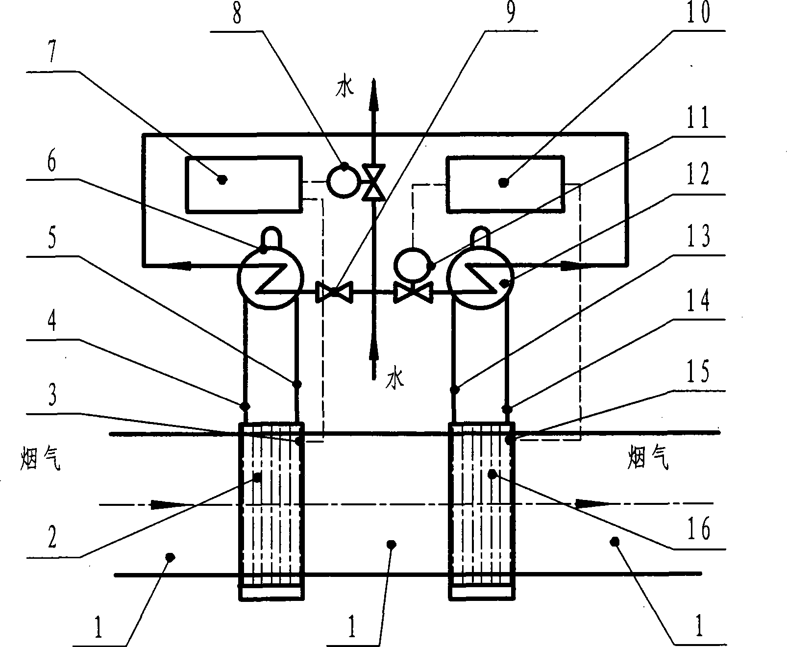
[0011] See the double-wall temperature composite phase-change heat exchanger shown in the accompanying drawing, which has a phase-change section and an automatic control device. The phase-change section is divided into a high-temperature phase-change section 2 and a low-temperature phase-change section 16, which are connected in series in the flue gas channel 1. The high-temperature phase change section 2 has a high-temperature section downcomer 4 and a high-temperature section riser 5 connected to the high-temperature section drum 6, and the low-temperature phase-change section 16 has a low-temperature section downcomer 13 and a low-temperature section riser 14 connected to the low-temperature section steam drum 12, and the high-temperature section Both the steam drum 6 and the low-temperature section steam drum 12 are connected with desalted wate...


PUM


Abstract

The invention discloses a composite phase change heat exchanger with double wall temperatures. A phase change section is divided into a high-temperature phase change section and a low-temperature phase change section that are serially connected in a flue gas channel, a descending pipe and an ascending pipe of the high-temperature phase change section are communicated with a steam header of the high-temperature section, a descending pipe and an ascending pipe of the low-temperature phase change section are communicated with a steam header of the low-temperature section, and a desalted water pipeline used for heat exchange is respectively connected in the steam header of the high-temperature section and the steam header of the low-temperature section; an automatic control device adjusts and controls the flow of desalted water in the high-temperature section and wall surface temperature of the high-temperature phase change section, and simultaneously adjusts and controls the flow of the desalted water in steam header of the low-temperature section and wall surface temperature of the low-temperature phase change section. Temperature control of different wall surfaces of the two phase change sections separates flue gas into two temperature decreasing sections, reduces the temperature decreasing difference between each temperature decreasing section, reasonably distributes the heat flow density between heated surface tube banks of each phase change section, and can not only ensure good global heat conductivity with temperature decreasing value of the flue gas larger than 60 DEG C and improve the afterheat utilization rate, but also can satisfy the higher output temperature requirement of the heated desalted water by setting proper wall temperature of the high-temperature section.

Description

[technical field] [0001] The invention relates to a device for recovering and utilizing boiler flue gas waste heat, specifically a double-wall temperature composite phase-change heat exchanger that connects two phase-change heat exchangers in series in the flue gas duct and controls different wall temperatures to recover flue gas waste heat device. [Background technique] [0002] Economizers and air preheaters are usually installed in the exhaust duct of power plant boilers, which absorb part of the waste heat of the flue gas. 3 Existence of flue gas outlet temperature of the heating surface at the tail of the air preheater is limited, and the exhaust gas temperature is too low will cause the wall temperature of the heating surface to be lower than the acid dew point of the flue gas, resulting in serious condensation corrosion and ash blocking, so the boiler The design exhaust gas temperature is usually 140°C to 160°C or higher. The composite phase change heat exchanger ca...

Claims


Application Information

Patent Timeline
Patent Type & Authority Applications(China)
IPC IPC(8): F28D15/00F28F27/00
Inventor 杨本洛
Owner 杨本洛
Learn More