
Radar sensor for recording the traffic environment in motor vehicles

A radar sensor and traffic environment technology, applied in the field of radar sensors, can solve problems such as excessive or too small sensitivity of radar sensors, and achieve the effects of reducing quantity, reducing transmission power, and reducing interference

Inactive Publication Date: 2009-04-01
ROBERT BOSCH GMBH
View PDF3 Cites 25 Cited by
  • Summary
  • Abstract
  • Description
  • Claims
  • Application Information

AI Technical Summary

Problems solved by technology

However, the sensitivity of this radar sensor may be too high or low in certain traffic situations

Method used


Image

  • Radar sensor for recording the traffic environment in motor vehicles
  • Radar sensor for recording the traffic environment in motor vehicles
  • Radar sensor for recording the traffic environment in motor vehicles

Examples


Embodiment Construction

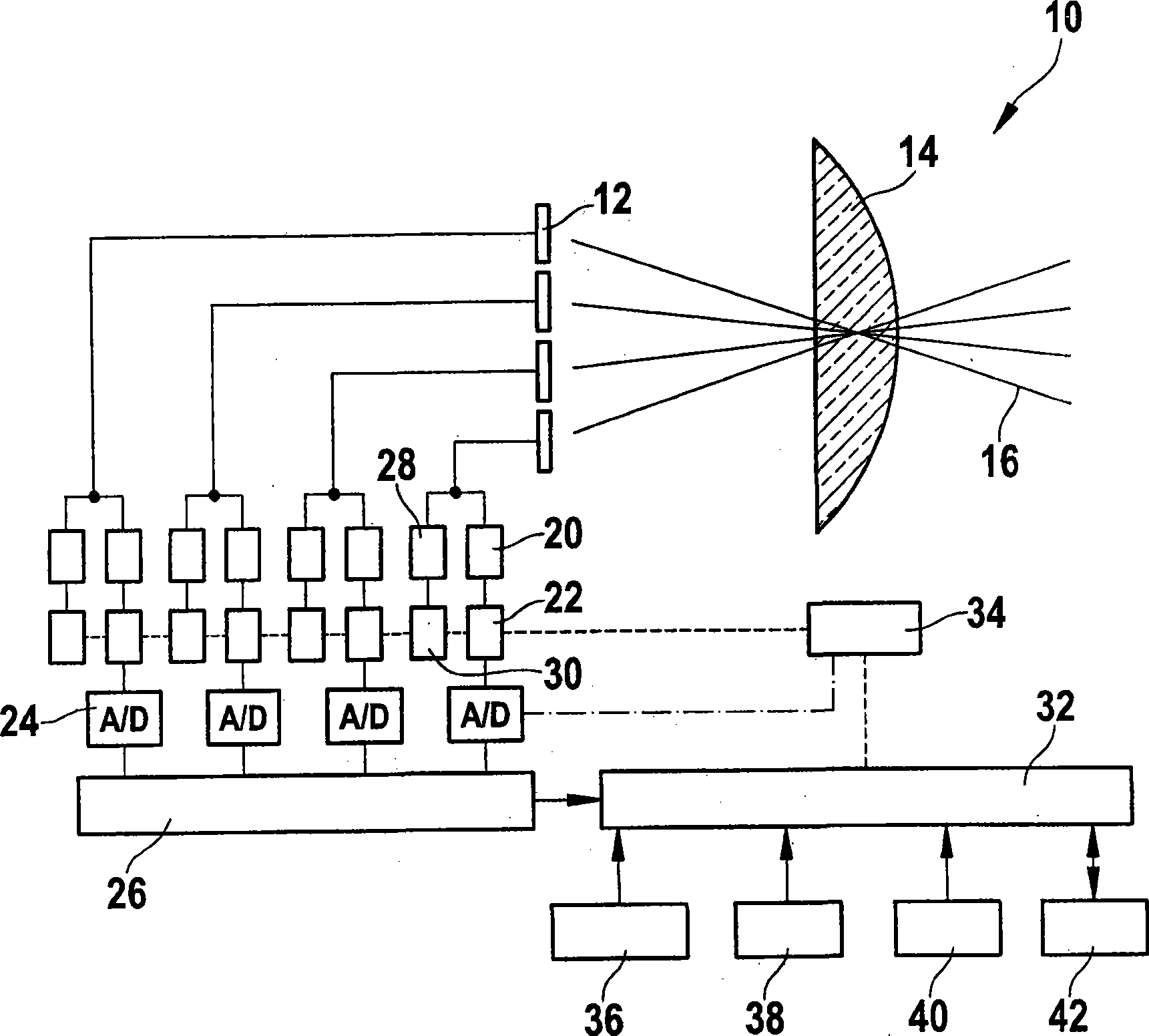
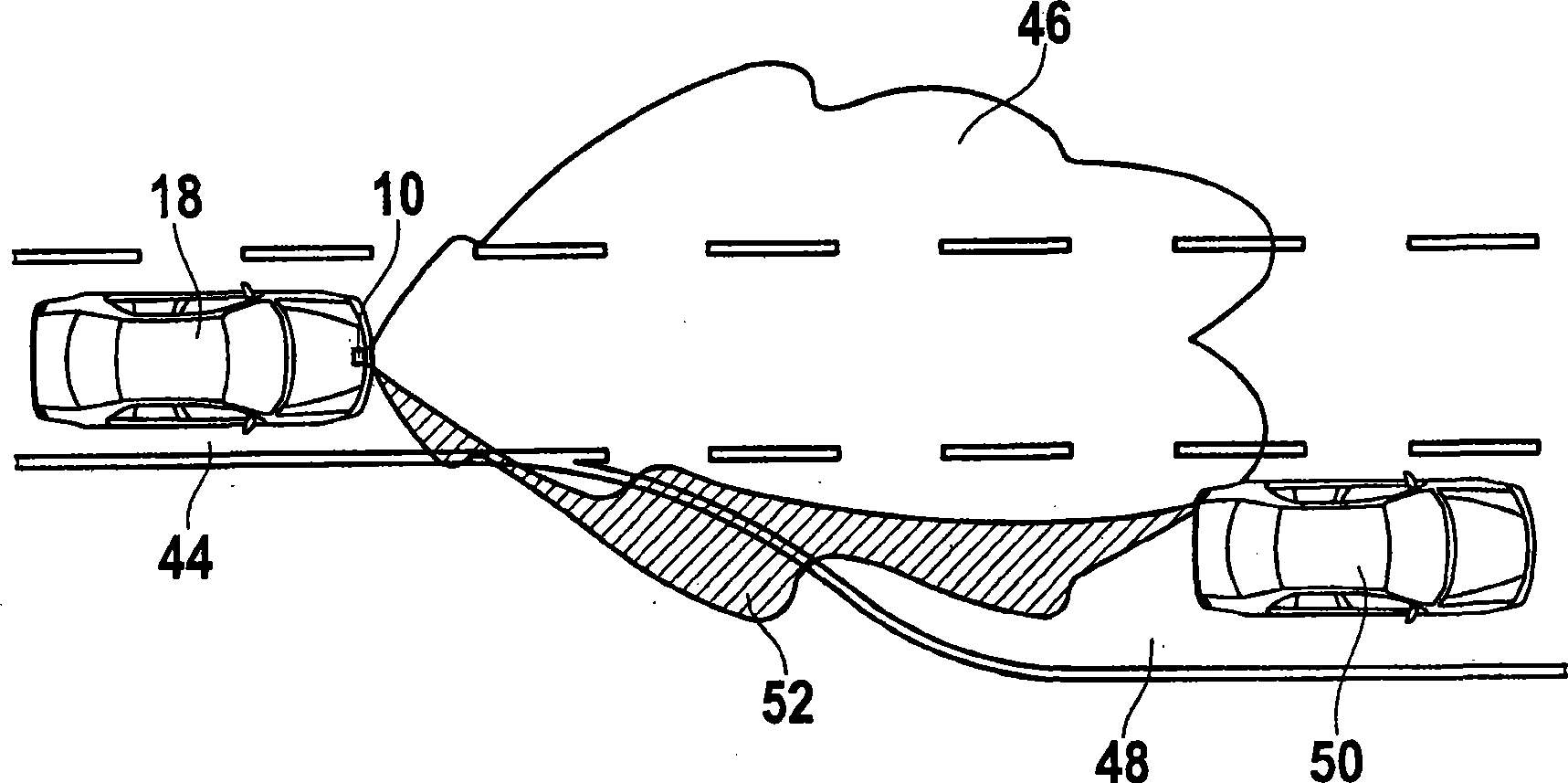
[0024] exist figure 1 In the example shown, the radar sensor 10 has four antennas 12, each of which can be used both for transmitting radar signals and for receiving reflected radar echoes, and these antennas are arranged close to a common radar The focal planes of the lenses 14 are such that they generate four radar beams 16 angularly offset from each other in azimuth. When the radar sensor 10 is integrated in a motor vehicle 18 ( figure 2 ) and pointing forward, good radiation to the traffic lane in front of the vehicle 18 can be achieved, and by comparing the amplitude and / or phase of the signals received by different antennas 12, the azimuth angle of the positioning object can also be learned .

[0025] Each antenna 12 is connected to an analog receiving unit 20 which is connected on its side via a receiving amplifier 22 to an analog-to-digital converter 24 which supplies a digital output signal to a computing circuit 26 . Furthermore, each antenna 12 is connected to a...


PUM


Abstract

The present invention relates to a radar sensor which is used for detecting the surrounding traffic environment in motor vehicle (18). The radar sensor comprises an adjustable transmitting amplifier and / or a receiving amplifier (22, 30) and an adjusting device (34) which is used for adjusting a transmitting gain and / or receiving gain. The invention is characterized in that an evaluating device (32) is designed for continuously evaluating the surrounding traffic environment and exerting effect to the adjusting device (34) according to the current evaluation.

Description

technical field [0001] The invention relates to a radar sensor for detecting surrounding traffic in a motor vehicle, with an adjustable transmitting amplifier and / or receiving amplifier and an adjusting device for adjusting the transmitting gain and / or receiving gain. Background technique [0002] From the document US 2006 / 044180 A1 is known a radar sensor of the form in which the level of the signal received for use by the calculation unit is returned to the regulating means (gain control) so that in a closed loop The strength of the received signal is controlled in the control system. [0003] In motor vehicles, radar sensors are used in conjunction with driver assistance systems - for example in adaptive speed control systems (adaptive cruise control; ACC) - to measure the distance and relative speed in order to automatically control the distance (of the own vehicle) to the vehicle ahead by intervening in the driving system and / or braking system of the own vehicle. Anot...

Claims


Application Information

Patent Timeline
IPC IPC(8): G01S7/03H01Q3/00G01S13/93G01S13/48G01S13/931
CPCG01S7/4052G01S7/4021G01S2007/403G01S2013/9325G01S2007/4013G01S2007/4091G01S2013/936G01S7/4026G01S7/4008G01S7/023G01S2013/9375G01S13/931G01S2013/9316G01S2013/93271G01S7/4013G01S7/403G01S7/4091
Inventor J·希尔斯贝彻A·詹德
Owner ROBERT BOSCH GMBH
Learn More