Polarizing plate, manufacturing method therefor, optical film and image display

A polarizing plate and film technology, applied in the field of polarizing plate and its manufacturing, can solve the problems of polarizing plate size change and unevenness, and achieve the effects of improving adhesive force, suppressing delamination, and high-speed production

Inactive Publication Date: 2009-04-01
NITTO DENKO CORP
View PDF11 Cites 17 Cited by
  • Summary
  • Abstract
  • Description
  • Claims
  • Application Information

AI Technical Summary

Problems solved by technology

However, the polarizing plate using the above-mentioned water-based adhesive has the problem that the size of the polarizing plate changes significantly due to

Method used


Image

  • Polarizing plate, manufacturing method therefor, optical film and image display
  • Polarizing plate, manufacturing method therefor, optical film and image display
  • Polarizing plate, manufacturing method therefor, optical film and image display

Examples


Embodiment 1

[0171] (Adhesive: curable component)

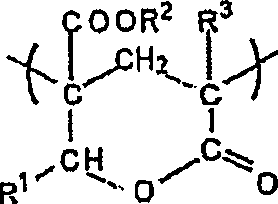
[0172] As the adhesive, N-hydroxyethylacrylamide was used.

[0173] (formation of easy-adhesive layer)

[0174] With respect to 100 parts by weight (solid content) of a polymer having a polyester skeleton (Superflex SF210, manufactured by Daiichi Kogyo Pharmaceutical Co., Ltd.), 10 parts by weight of 3-acryloyloxypropyltrimethoxysilane (KBM5103, Shin-Etsu Silicone Co., Ltd.), a forming material was prepared (solid content concentration: 11% by weight). Using a bar coater, apply this forming material to one side of a transparent protective film (lactone ring polymethyl methacrylate film) to a thickness of 0.3 μm, dry at 150°C, and form an easy Adhesive layer.

[0175] (Formation of polarizing plate)

[0176] Using a micro-gravure coating machine (gravure printing roll: #300, rotation speed 140% / line speed), on the easy-adhesive layer formed on the transparent protective film, apply the adhesive to form a thickness of 5 μm transparent ...

Embodiment 2~13、 comparative example 1~19

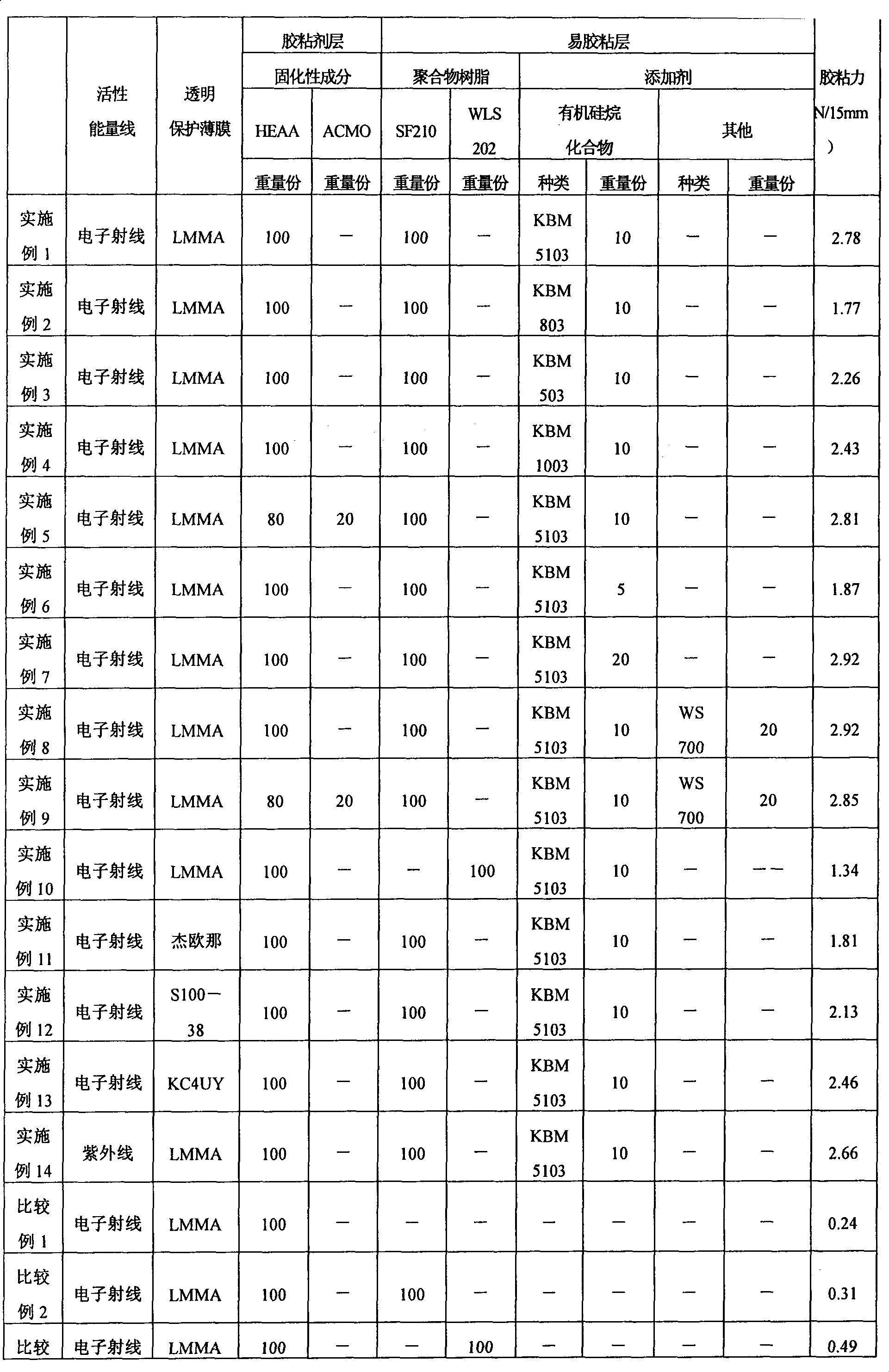
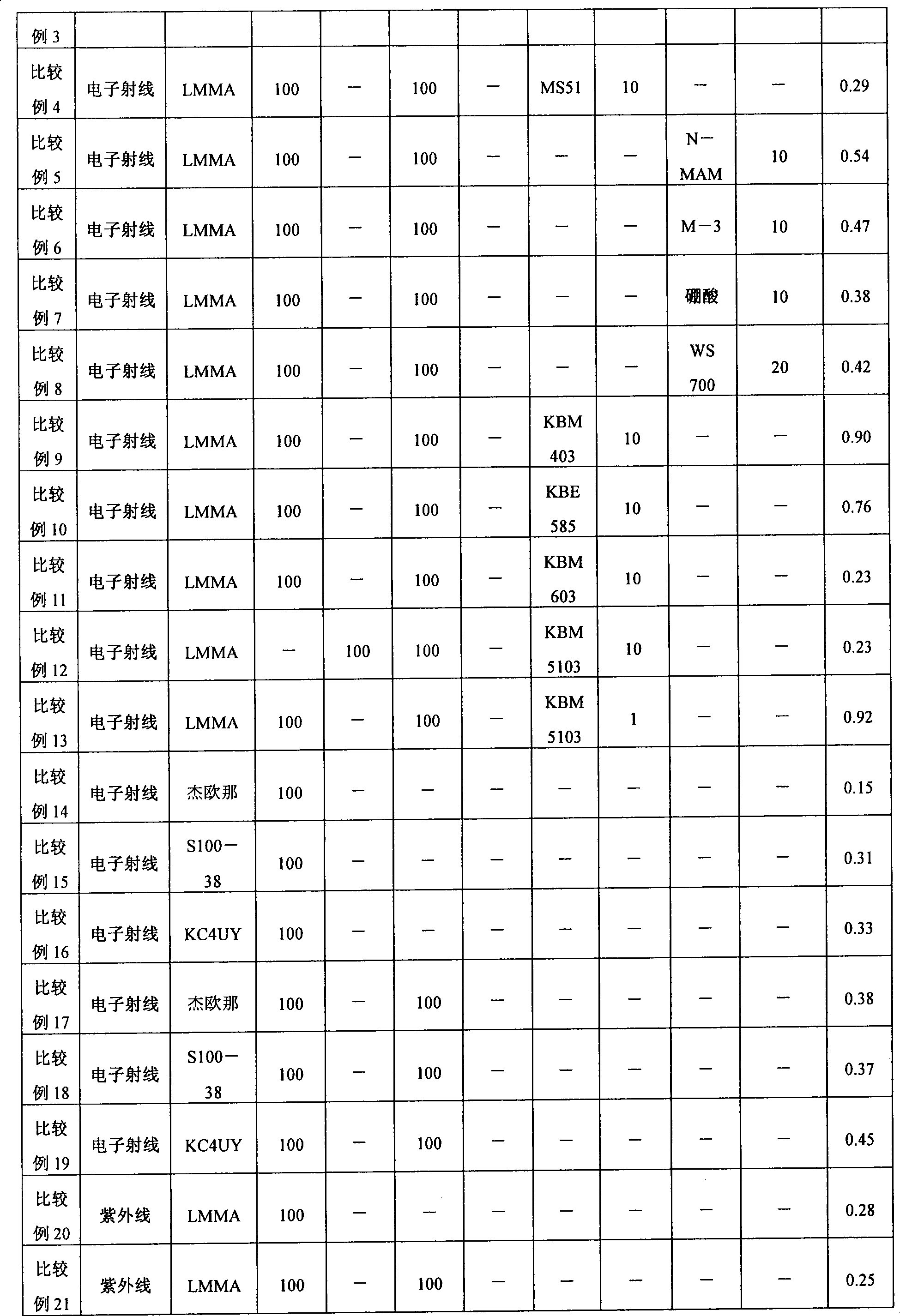
[0178] In Example 1, the type of transparent protective film, the type of adhesive (curable component), and its ratio when used in combination; the type of polymer resin forming the easy-adhesion layer, the type of additives, or their usage amounts are shown in Table 1. As shown, except this, it carried out similarly to Example 1, and obtained the polarizing plate.

Embodiment 14

[0180] (Adhesive: curable component)

[0181] 3 parts by weight of a photopolymerization initiator (manufactured by Chiba Special Chemicals Co., Ltd.; trade name Irgacure 127) was mixed with 100 parts by weight of N-hydroxyethylacrylamide, and used as an adhesive.

[0182] (Formation of polarizing plate)

[0183] Carry out in the same manner as in Example 1 (formation of an easily-adhesive layer), using a micro-gravure coating machine (gravure printing roll: #300, rotation speed 140% / line speed), on a transparent protective film (lactonization On the easy-adhesive layer formed on the polymethyl methacrylate film), the adhesive prepared in the above was coated to form a transparent protective film with an adhesive with a thickness of 5 μm. Next, the transparent protective film with an adhesive was bonded from both sides of the polarizing plate by a rolling mill. Ultraviolet rays were irradiated from the side (both sides) of the bonded transparent protective film to obtain a p...


PUM

PropertyMeasurementUnit
Thicknessaaaaaaaaaa

Abstract

The invention provides a polarizing plate using active energy ray-cured adhesive to adhere polarizing sheet and transparent protective film and having good adhesion. The polarizing plate is a polarizing plate provided with a transparent protective film placed on at least one side of the polarizer; and an adhesive layer and an adhesion facilitating layer interposed in this order from the polarizer side between the polarizer and the transparent protective film, wherein the adhesive layer is formed with an active energy ray-curable adhesive that contains a hydroxyl group-containing N-substituted amide monomer as a curable component, and the adhesion facilitating layer is formed with a polymer resin composition that contains 100 parts by weight of a polymer resin and 3 to 30 parts by weight of an organosilane compound having at least one functional group selected from an acryloyl group, a methacryloyl group, a vinyl group, and a mercapto group.

Description

technical field [0001] The present invention relates to a polarizing plate and a manufacturing method thereof. This polarizing plate can be used alone or as an optical film laminated to form an image display device such as a liquid crystal display device (LCD), an organic EL display device, a CRT, or a PDP. Background technique [0002] Liquid crystal display devices are rapidly spreading in the market for clocks, mobile phones, PDAs, notebook computers, monitors for personal computers, DVD players, TVs, and the like. A liquid crystal display device visualizes a change in a polarization state due to switching of liquid crystals, and a polarizing plate can be used according to the display principle. In particular, applications such as TVs require higher and higher brightness and contrast ratios and wider viewing angles. For polarizing plates, higher transmittance, higher polarization degrees, and higher color reproducibility are also required. [0003] As a polarizer, for e...

Claims


Application Information

Patent Timeline
IPC IPC(8): G02B5/30G02B1/10B32B37/12G02F1/1335G09F9/00C09J4/02C08L67/00C08K5/54
CPCB32B7/02B32B7/12B32B37/12B32B2307/42C08J5/18G02B1/14G02B5/3041G02F1/133528
Inventor 八重樫将宽池田哲朗中野勇树赤利玲子铃木畅
Owner NITTO DENKO CORP
Why Eureka
Try Eureka