

Polarizing plate, manufacturing method therefor, optical film and image display
A polarizing plate and film technology, applied in the field of polarizing plate and its manufacturing, can solve problems such as unevenness, change of polarizing plate size, etc., and achieve the effects of improving adhesive force, high-speed production, and suppressing delamination
Inactive Publication Date: 2010-08-11
NITTO DENKO CORP
View PDF14 Cites 0 Cited by
- Summary
- Abstract
- Description
- Claims
- Application Information
AI Technical Summary
Problems solved by technology
However, the polarizing plate using the above-mentioned water-based adhesive has the problem that the size of the polarizing plate changes significantly due to the heat of the backlight, which becomes uneven, and a black display is visible in a part of the entire screen. Whitening so-called light leakage (unevenness)
Method used
View moreImage
Smart ImageViewing Examples

Examples
Embodiment 1
Embodiment 2~13、 comparative example 1~19
Embodiment 14
Login to View More PUM
| Property | Measurement | Unit |
|---|---|---|
| thickness | aaaaa | aaaaa |
| thickness | aaaaa | aaaaa |
| glass transition temperature | aaaaa | aaaaa |
Abstract
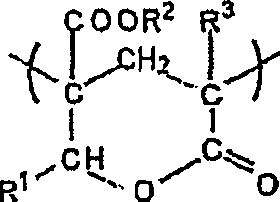
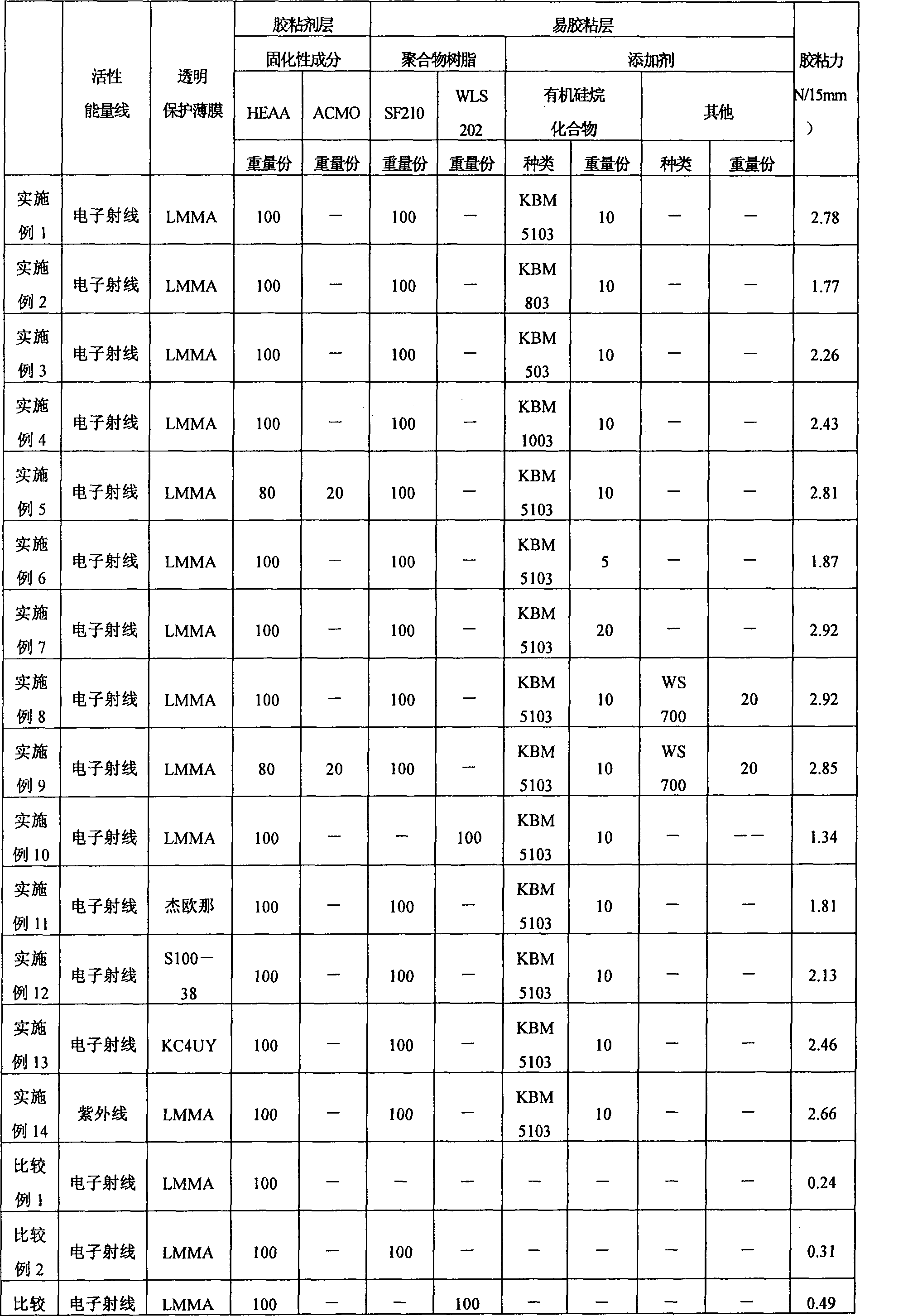
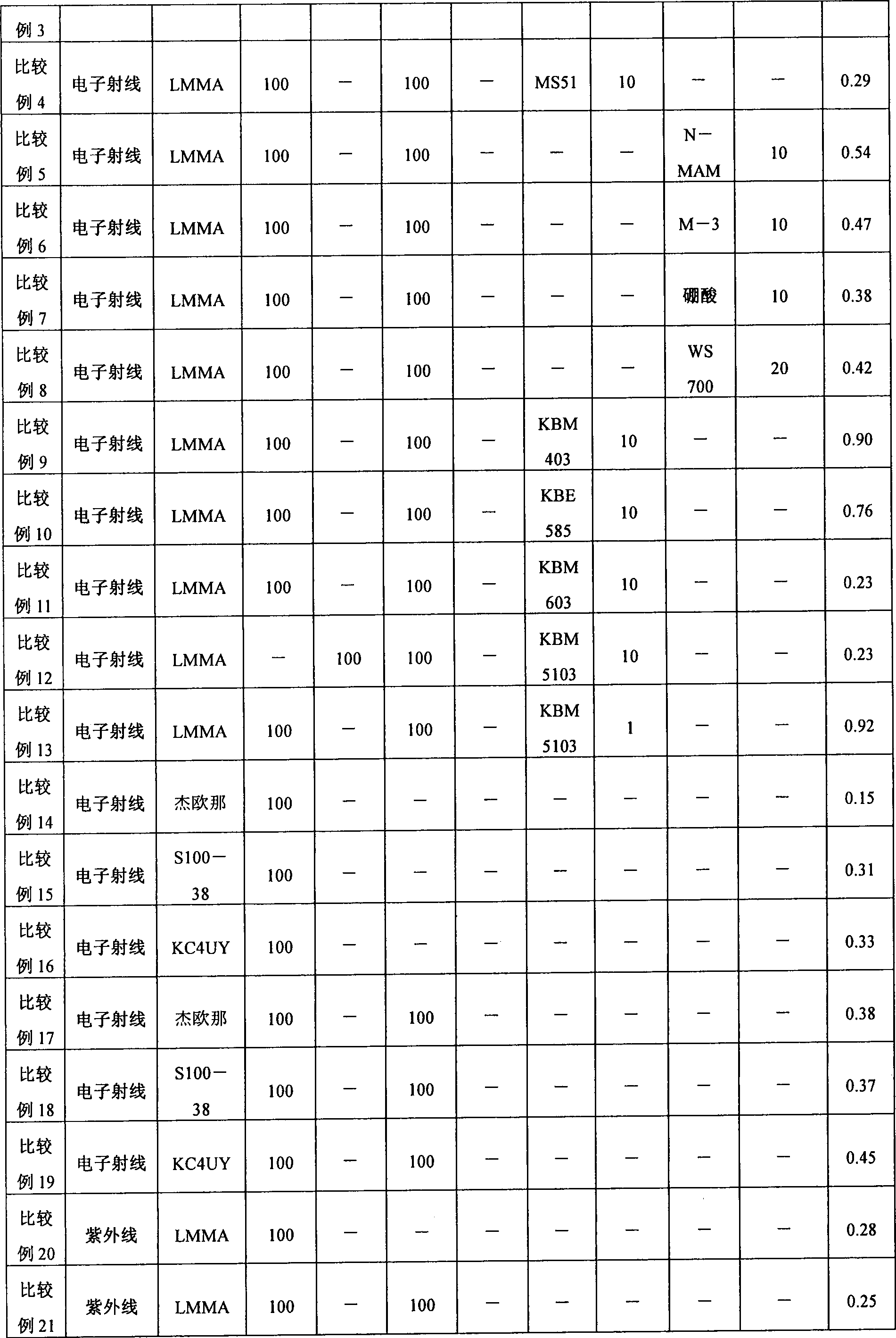
The invention provides a polarizing plate using active energy ray-cured adhesive to adhere polarizing sheet and transparent protective film and having good adhesion. The polarizing plate is a polarizing plate provided with a transparent protective film placed on at least one side of the polarizer; and an adhesive layer and an adhesion facilitating layer interposed in this order from the polarizerside between the polarizer and the transparent protective film, wherein the adhesive layer is formed with an active energy ray-curable adhesive that contains a hydroxyl group-containing N-substitutedamide monomer as a curable component, and the adhesion facilitating layer is formed with a polymer resin composition that contains 100 parts by weight of a polymer resin and 3 to 30 parts by weight of an organosilane compound having at least one functional group selected from an acryloyl group, a methacryloyl group, a vinyl group, and a mercapto group.
Description
technical field The present invention relates to a polarizing plate and a manufacturing method thereof. This polarizing plate can be used alone or as an optical film laminated to form an image display device such as a liquid crystal display device (LCD), an organic EL display device, a CRT, or a PDP. Background technique Liquid crystal display devices are rapidly spreading in the market for clocks, mobile phones, PDAs, notebook computers, monitors for personal computers, DVD players, TVs, and the like. A liquid crystal display device visualizes a change in a polarization state due to switching of liquid crystals, and a polarizing plate can be used according to the display principle. In particular, applications such as TVs require higher and higher brightness and contrast ratios and wider viewing angles. For polarizing plates, higher transmittance, higher polarization degrees, and higher color reproducibility are also required. As a polarizer, for example, an iodine-based ...
Claims
Login to View More Application Information
Patent Timeline
 Patent Type & AuthorityPatents(China)
IPC IPC(8): G02B5/30G02B1/10B32B37/12G02F1/1335G09F9/00C09J4/02C08L67/00C08K5/54
CPCB32B7/02B32B7/12B32B37/12B32B2307/42C08J5/18G02B1/14G02B5/3041G02F1/133528
Inventor八重樫将宽池田哲朗中野勇树赤利玲子铃木畅
OwnerNITTO DENKO CORP