
Bioreactor for producing tissue engineering products

A technology of bioreactor and production organization, which is applied in the direction of specific-purpose bioreactor/fermenter, bioreactor/fermenter combination, tissue cell/virus culture device, etc. And problems such as too many pipelines and large reactor volume, etc., to achieve the effect of reducing the occupied area of ​​the equipment, wide application range and good scalability

Active Publication Date: 2009-04-08
威力保生物技术(成都)有限公司
View PDF2 Cites 12 Cited by
  • Summary
  • Abstract
  • Description
  • Claims
  • Application Information

AI Technical Summary

Problems solved by technology

However, this bioreactor has the following disadvantages: first, the support is vertical, and the number of cells adhered to the support is limited; second, the production of the operating unit is relatively complicated; third, the required amount of culture medium is large; The volume is relatively large. Fifth, it is only suitable for the cultivation of synthetic scaffold products. Sixth, it cannot cultivate double-layer tissue engineered skin, and it cannot be used for air-liquid interface culture.
There is also a CN1560225A titled "Perfusion Bioreactor System Constructed in Vitro with Double-Layer Active Skin" published on January 5, 2005, which includes a liquid addition device, a perfusion bioreactor, a liquid collection device, and a liquid return device And gas supply device, its disadvantage is large volume, too many control valves and pipelines
The bioreactors of the above-mentioned prior art can only be used for the cultivation of tissue engineered skin, but are not suitable for the in vitro construction of other tissue engineering products such as bone, cartilage, tendon, etc.

Method used


Image

  • Bioreactor for producing tissue engineering products
  • Bioreactor for producing tissue engineering products
  • Bioreactor for producing tissue engineering products

Examples


Embodiment Construction

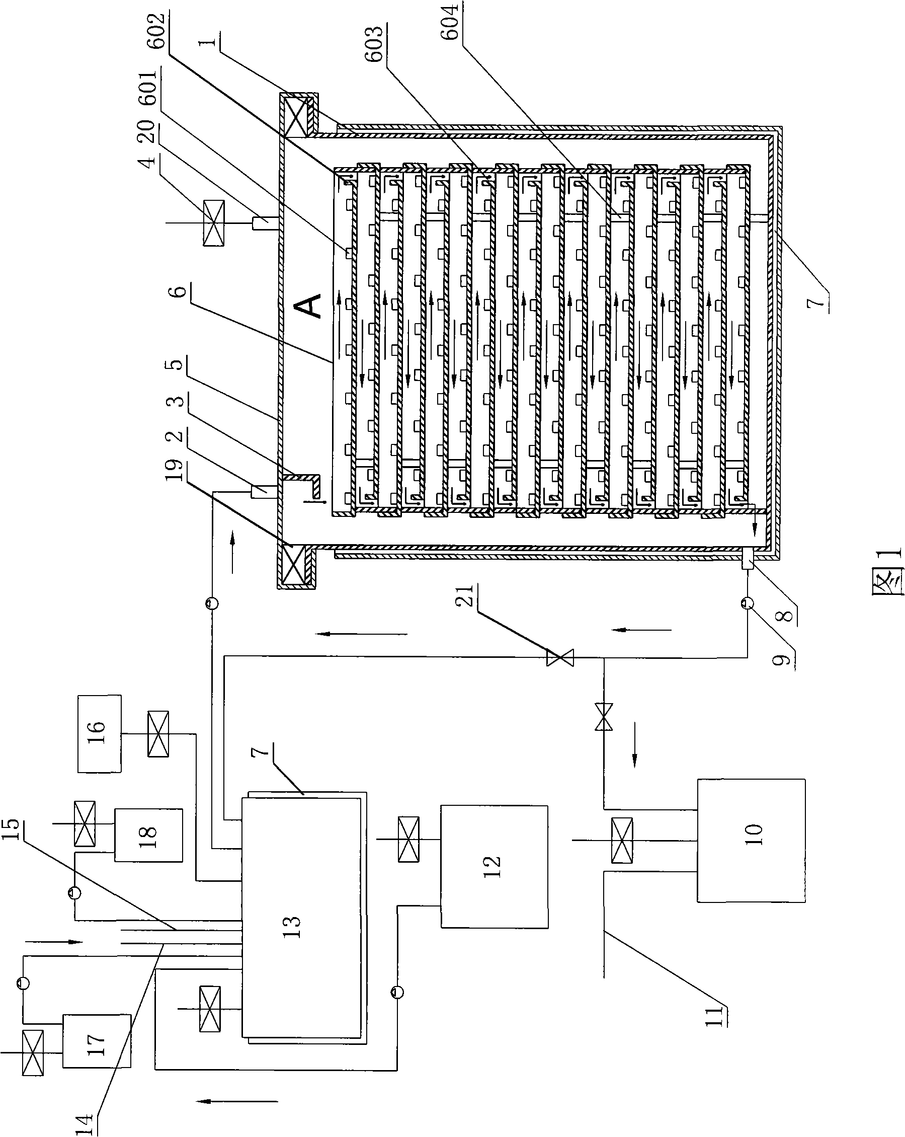
[0018] The specific structure of the bioreactor of the present invention will be further described below in conjunction with the accompanying drawings.

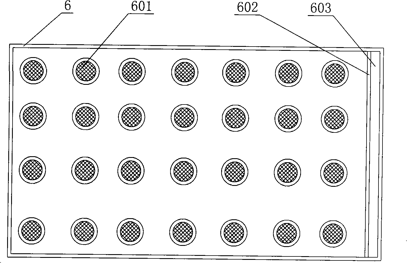
[0019]A bioreactor for producing tissue engineering products, including a waste liquid bottle 10, a liquid replacement bottle 12, a liquid storage bottle 13, a four-gas mixer 16, an acid liquid bottle 17, an alkali liquid bottle 18, and a reaction box Body 1, reaction box cover 5, layer plate 6, thermostatic jacket 7 and sealing gasket 19 assembled biological reaction box A; reaction box cover 5 is provided with liquid inlet 2 and air exchange port 20, near the liquid inlet 2 The bottom surface of the reaction box cover is provided with a liquid baffle 3, the thermostatic jacket 7 is arranged on the periphery of the reaction box body 1, and the lower part of one side of the reaction box body 1 is provided with a liquid outlet 8 passing through the thermostatic jacket, and the sealing gasket 19 is installed on Between the reac...


PUM


Abstract

The invention relates to a bioreactor for producing tissue engineering products, which comprises a waste liquid bottle, a fluid replacement bottle, a liquid storage bottle, a four-nature mixer, an acid liquor bottle, an alkali liquor bottle and a bioreaction box assembled by a reaction box body, a reaction box cover, layer boxes, a constant temperature jacket and a sealing gasket. The layer boxes are superposed from bottom to top in an alternate manner of forward direction and backward direction in the reaction box; the overflow gutter of the pan of the upper layer is over the opposite end of the overflow gutter of the pan of the lower layer, and one end of the overflow gutter of the pan at the lowest layer is close to the liquid outlet of the reaction box body and one end of the positioning pin of the pan at the uppermost layer is arranged below a liquid baffle. Compared with the prior art, the bioreactor has good expansibility, simple structure, small volume, few pipes, high universal property and wide application range, is suitable for mass production, not only applicable for the culture of tissue engineering skin at gas-liquid interfaces to produce tissue engineering skin but also for the systemization and production of scaffold tissue engineering products (such as bones, cartilage, muscle tendon and the like).

Description

technical field [0001] The invention belongs to a human tissue culture device, and relates to a bioreactor for producing tissue engineering products, especially tissue engineering skin. Background technique [0002] Tissue engineering is an emerging interdisciplinary field developed in the past 30 years. Its ultimate goal is to produce products for restoring, maintaining, or enhancing the structure and function of human damaged organs or tissues, such as tissue engineered skin, bone, cartilage, tendon etc. Tissue-engineered skin is the fastest-growing category of products, and several products are currently in clinical use. Apligraf produced by Organogenesis Company of the United States is the first tissue-engineered skin containing epidermis and dermis at the same time. It is represented by collagen as a scaffold. Its production process adopts the traditional static culture method. For cell-forming gel, inoculate keratinocytes on the surface after 4-6 days of culture, and...

Claims


Application Information

Patent Timeline
IPC IPC(8): C12M3/00C12M1/36
CPCC12M41/22C12M23/34C12M21/08
Inventor 伍津津
Owner 威力保生物技术(成都)有限公司
Learn More